Contoured eye shadow applicator system and make-up method

a makeup applicator and eye shadow technology, applied in the field of makeup applicators, can solve the problems of difficult use of rounded sponge pads, convex, and difficult to apply eye shadow uniformly, and achieve the effect of quick and accurate application of eye shadow and greater length

Inactive Publication Date: 2011-05-31
COLE CHRISTINA M
View PDF13 Cites 32 Cited by
  • Summary
  • Abstract
  • Description
  • Claims
  • Application Information

AI Technical Summary

Problems solved by technology

For example, the applicant has observed that, as a result of the convex or angular shape of the ends of such applicators, they do not easily apply eye shadow uniformly over the eye lid and the rounded surfaces between the eye lid and the eye brow without a substantial number of strokes and care on the part of the user.
A convex, rounded sponge pad applicator is particularly difficult to utilize, as it fails to distribute eye shadow uniformly over the rounded surfaces of the eye region due to the point or line contact such applicators make with such rounded surfaces.
The end result is that the user must spend an inordinate amount of time and effort to get the intended coverage over the closed eye lid and brow region.
Because of the necessity of numerous wipings of such applicators to the pad of eye shadow make-up and numerous strokes between the applicator and the user, they often become worn down quickly and sometimes disconnect from their handles, requiring replacement.
While brushes having angled profiles are somewhat better in applying eye shadow in the corners of the eye region, they too apply eye shadow make-up non-uniformly along the rounded surface of a closed eyelid.
In all cases, the need for multiple rubbings of such applicators into the pad of relatively expensive eye shadow make-up, and multiple strokes before the desired application of make-up has taken place around the eye area, results in a pre-mature wearing down of the pad of eye shadow make-up, and large amounts of time, effort, and concentration on the part or the user to achieve a uniform application of eye shadow over the eye region.

Method used


Image

  • Contoured eye shadow applicator system and make-up method
  • Contoured eye shadow applicator system and make-up method
  • Contoured eye shadow applicator system and make-up method

Examples


Embodiment Construction

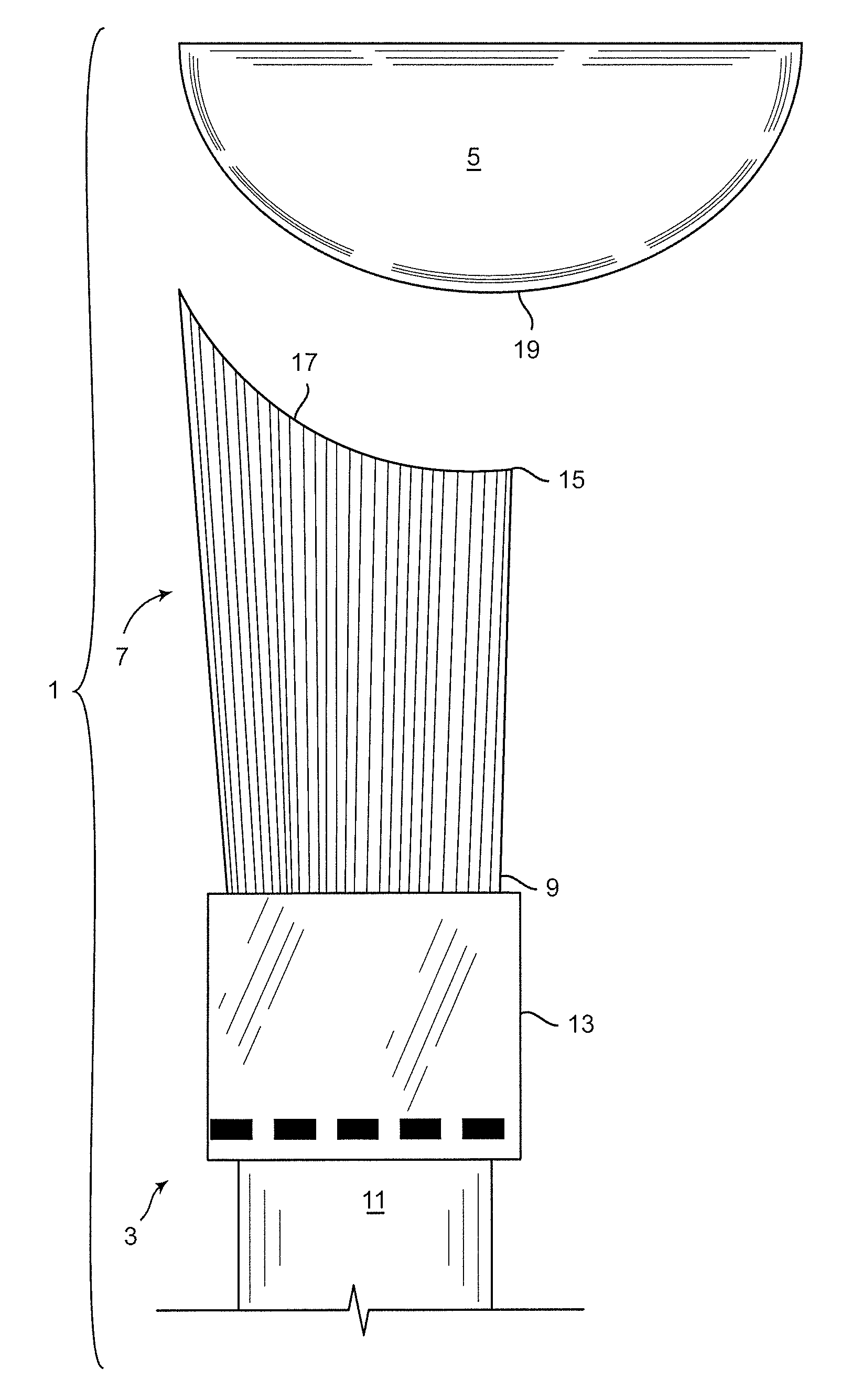
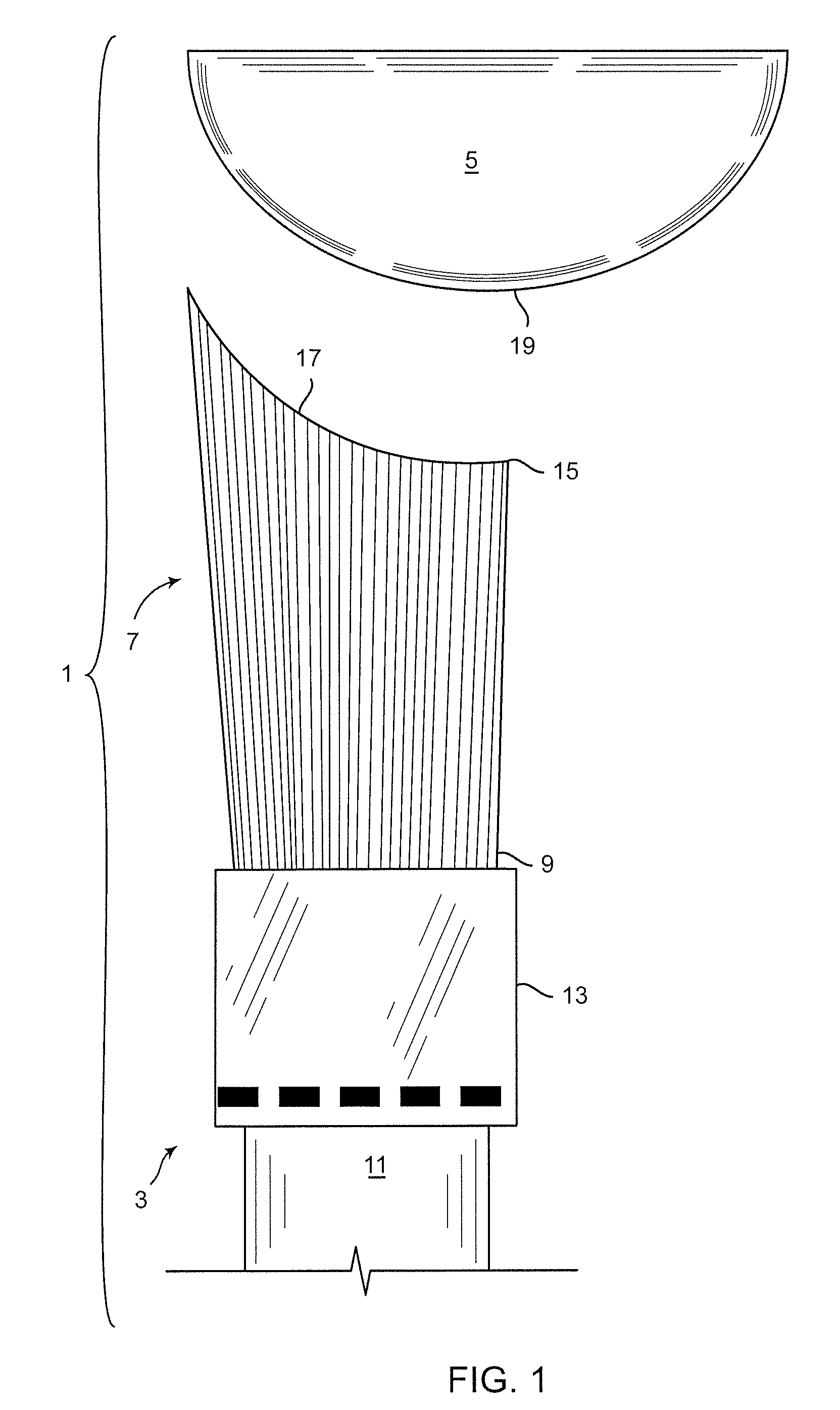
With reference to FIG. 1, wherein like numerals designate like components throughout all the several figures, the eye shadow applicator system 1 of the invention comprises an applicator 3 in combination with a convex pad 5 of eye shadow make-up. The applicator 3 includes a resilient body which may take the form of a sponge pad (not shown) or a bundle of bristles 7. The proximal end 9 of the bundle of bristles 7 is connected to a handle 11 by means of a collar member 13. The distal end 15 of the bundle of bristles 7 has a concave shape 17 which is not only complementary to the outer surface 19 of the convex pad 5 of eye shadow make-up, but is also complementary in shape to the closed eye lid of a user.

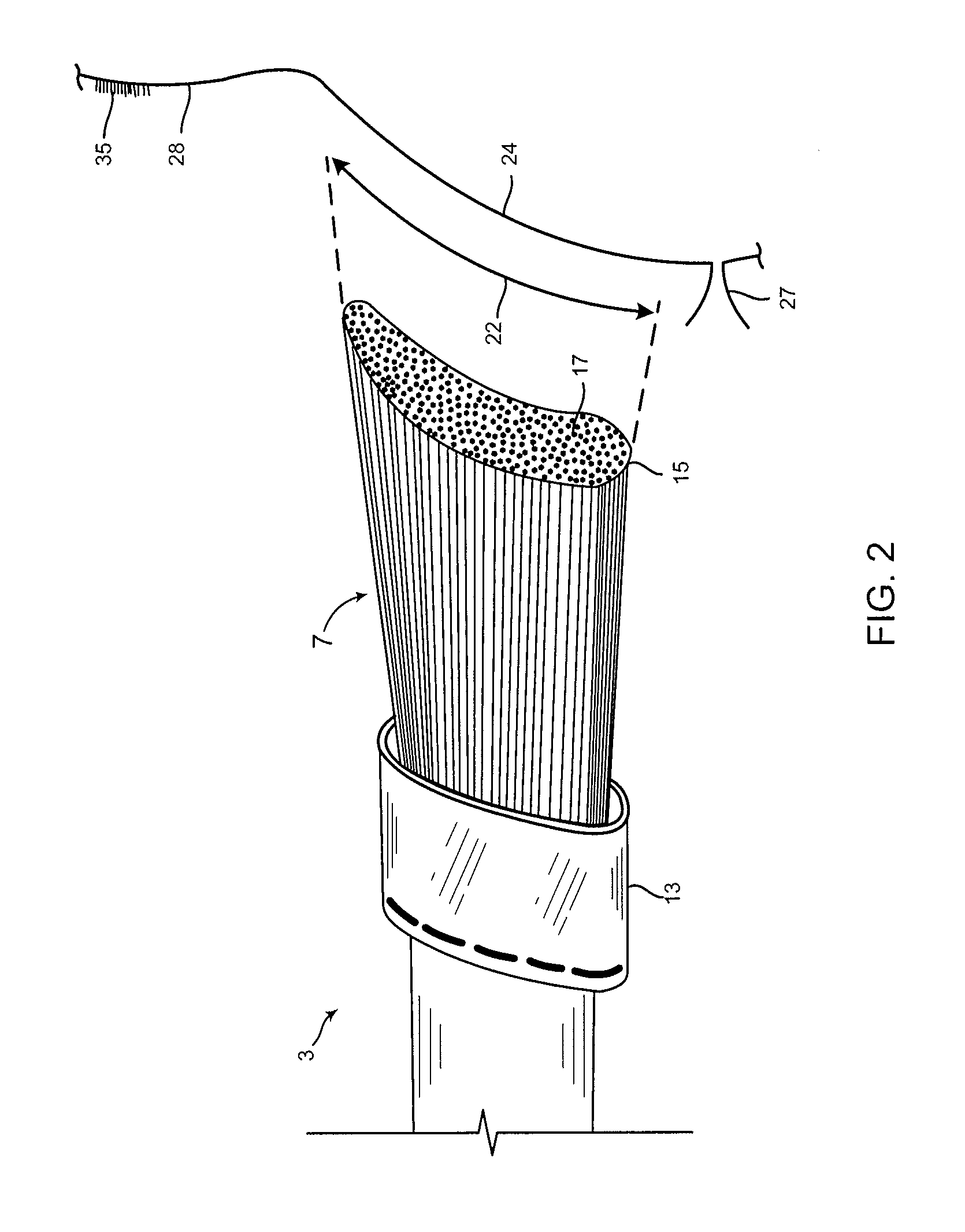
The relationship between the shape and extent of the distal end 15 of the bundle of bristles 7 and the closed eye lid of a user is best seen in FIG. 2, where the distal end 17 of the bristle bundle 7 is illustrated adjacent to a schematic profile of the eye region 21 of a user. Here, it...


PUM


Abstract

An applicator system for applying eye shadow is provided that includes flexible body, which may be a bundle of bristles, having a proximal end secured to a handle, and a distal end having a concave shape that is substantially complementary to a portion of a closed eye lid. The concave shape is asymmetrical so that one end of the bristle bundle extends farther out than the other end to facilitate the application of make-up under the brow region and in the corners of the eye area. Eye make-up is preferably applied to the concave brush by a convex-shaped pad of eye shadow in the shape of a cylindrical section having a convex profile that is complementary in shape to the concave profile of the distal end of the bristle bundle.

Description

FIELD OF THE INVENTIONThis invention generally relates to make-up applicators, and is specifically concerned with an applicator for applying eye shadow whose working end is in a concave shape that is substantially complementary to the shape of a closed eye lid.Eye shadow applicators are well known in the prior art. Such applicators include brushes having either a rounded or angular end, or sponge pads having a convex, rounded profile. In use, eye shadow is first applied to the applicator end of the brush or sponge by wiping the same across a pad of selected eye shadow make-up. The user then applies the eye shadow present on the end of the bristles or sponge to the area over the eye lid and beneath the eye brow.While presently known eye shadow applicators are generally effective for their intended purpose, the applicant has observed a number of shortcomings in the structure and operation of such prior art applicators in which substantial improvement may be possible. For example, the ...

Claims


Application Information

Patent Timeline
Patent Type & Authority Patents(United States)
IPC IPC(8): A45D40/26
CPCA45D40/262A46B9/021A46B2200/1046
Inventor COLE, CHRISTINA M.
Owner COLE CHRISTINA M
Why Eureka
Try Eureka