
Display base including torque limiter and torque limiter

a technology of display base and torque limiter, which is applied in the direction of instruments, slip couplings, and electric apparatus casings/cabinets/drawers, etc., can solve the problems of disadvantageous increase in number of components of transmission gear portion, etc., to achieve the effect of convenient transmission

Inactive Publication Date: 2011-05-31
FUNAI ELECTRIC CO LTD
View PDF22 Cites 16 Cited by
  • Summary
  • Abstract
  • Description
  • Claims
  • Application Information

AI Technical Summary

Benefits of technology

[0016]In the aforementioned display base according to the first aspect, the driven gear member constituting the torque limiter preferably integrally includes stop sections for inhibiting the drive gear member from slipping off to a second side, provided between the plurality of support sections of the driven gear member. According to this structure, the driven gear member integrally includes stop sections for inhibiting the drive gear member from slipping off to a second side, provided between the plurality of support sections of the driven gear member. According to this structure, the stop sections of the driven gear member come into contact with the drive gear member and hence the drive gear member can be easily inhibited from slipping off from the driven gear member to the second side of the drive gear member also when the drive gear member rotates at prescribed driving torque or more and slips on the outer peripheral surfaces of the support sections of the driven gear member.
[0033]In the aforementioned torque limiter according to the second aspect, the first rotating member preferably integrally includes a driven gear portion, and the second rotating member preferably integrally includes a drive gear portion. According to this structure, driving torque transmitted to the second rotating member can be easily transmitted from the first rotating member to other rotating member with the gear portion.

Problems solved by technology

Therefore, in a case where the torque limiter described in Japanese Patent Laying-Open No. 7-190083 is applied to a base of display (liquid crystal display, for example) comprising a driving source turning a display screen portion and a transmission gear portion for transmitting the driving force of the driving source to a turning portion, the number of components of the transmission gear portion is disadvantageously increased.
Therefore, in a case where the gear with a torque limiter described in Japanese Patent Laying-Open No. 2004-360809 is applied to a base of display (liquid crystal display, for example) comprising a driving source turning a display screen portion and a transmission gear portion for transmitting the driving force of the driving source to a turning portion, the number of components of the transmission gear portion is disadvantageously increased.
Therefore, in a case where the viscous joint described in Japanese Patent Laying-Open No. 6-11016 is applied to a base of display (liquid crystal display, for example) comprising a driving source turning a display screen portion and a transmission gear portion for transmitting the driving force of the driving source to a turning portion, the number of components of the transmission gear portion is disadvantageously increased.

Method used


Image

  • Display base including torque limiter and torque limiter
  • Display base including torque limiter and torque limiter
  • Display base including torque limiter and torque limiter

Examples


Embodiment Construction

[0049]An embodiment of the present invention will be hereinafter described with reference to the drawings.

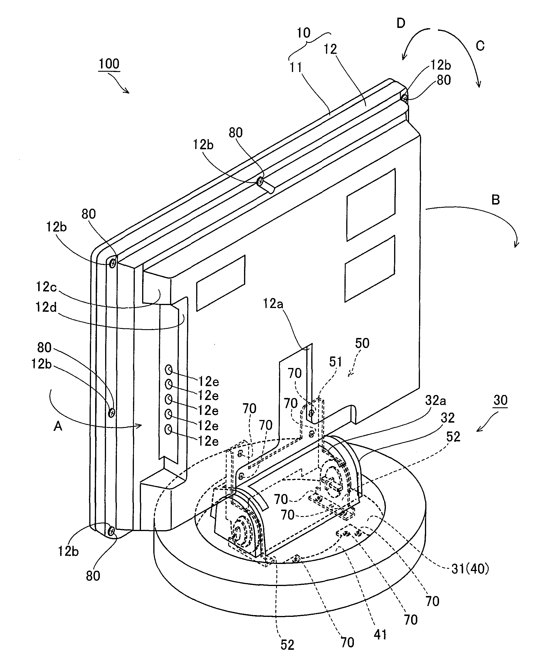
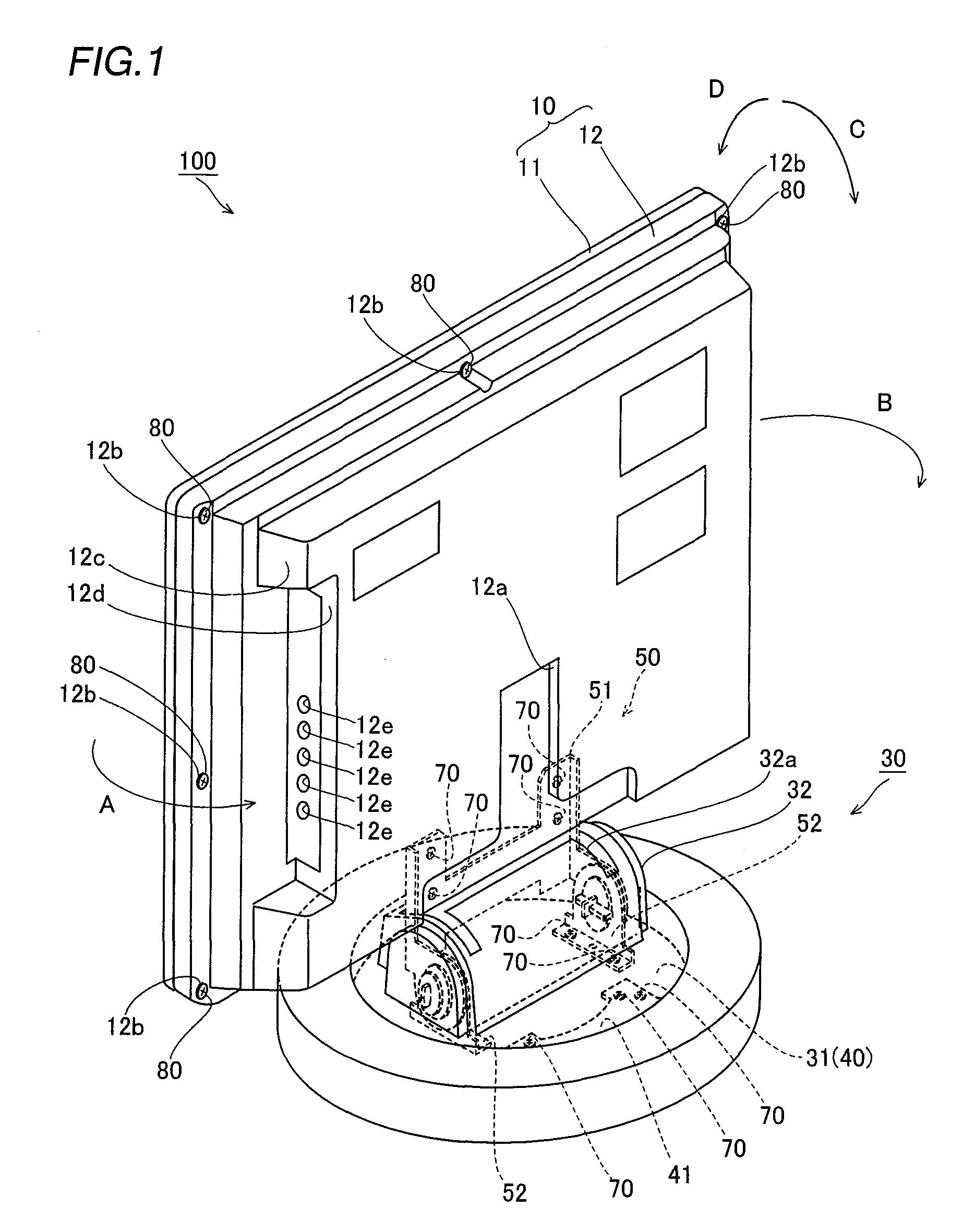
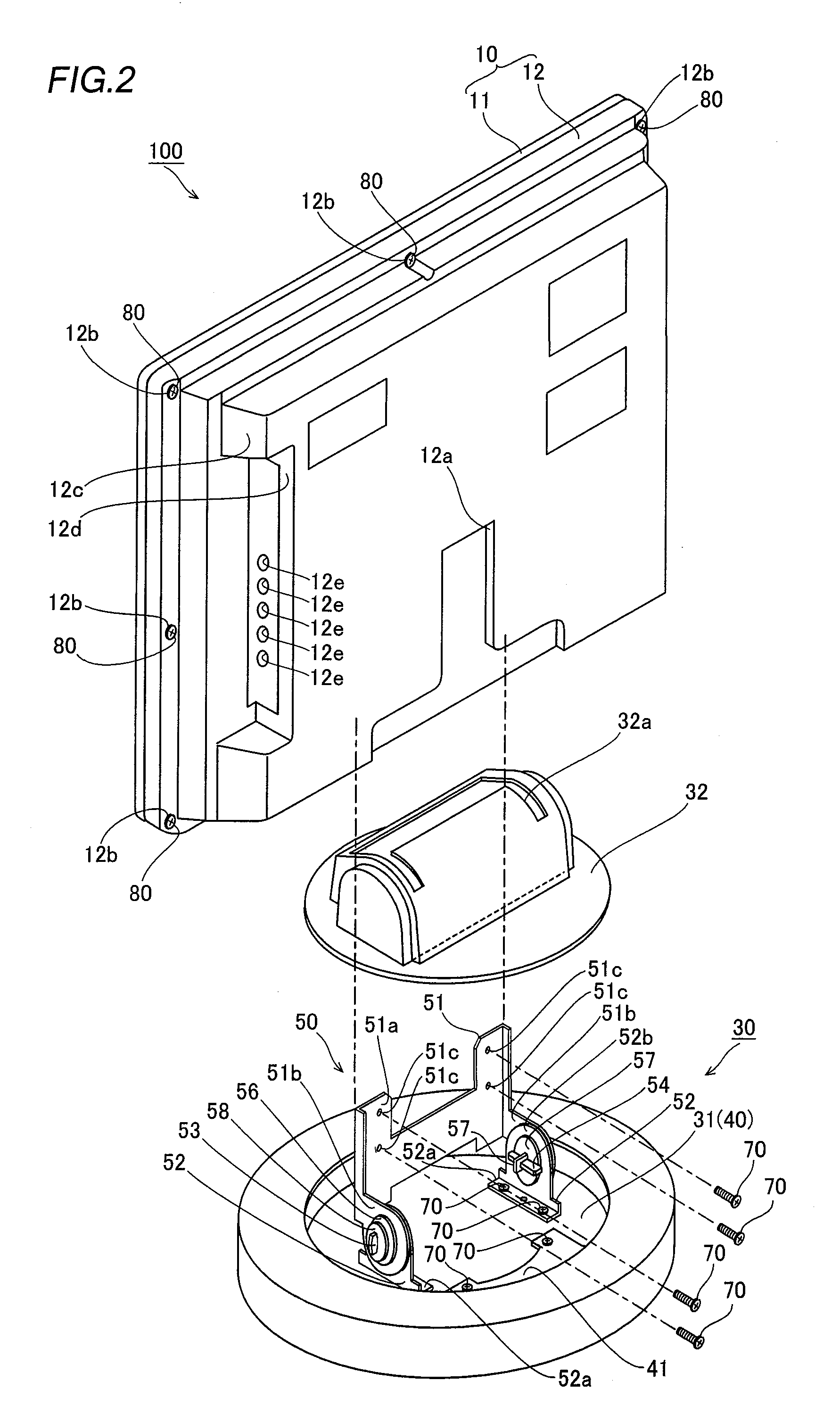
[0050]A structure of a torque limiter and a base provided with the torque limiter according to the embodiment of the present invention will be now described with reference to FIGS. 1 to 13. This embodiment of the present invention is applied to a base of a liquid crystal display, which is an exemplary of a display.

[0051]A liquid crystal display 100 according to the embodiment of the present invention comprises a display body 10 and a base 30 capable of turning the display body 10 in a horizontal direction (along arrows A and B) by a prescribed angle (±30 degrees, for example) and inclining in a vertical direction (along arrows C and D) by a prescribed angle, as shown in FIG. 1. The display body 10 is an example of the “display screen portion” in the present invention.

[0052]The base 30 is constituted by a display screen support mechanism 50 supporting a display body 10, a turning...


PUM


Abstract

A display base including a torque limiter capable of inhibiting the number of components from increase and the torque limiter are obtained. This display base includes a driving source turning a display screen portion and a transmission gear portion for transmitting driving force of the driving source to a turning portion. The transmission gear portion includes a torque limiter having a driven gear member integrally provided with a plurality of support sections formed concentrically with rotational axis, a drive gear member fitted onto an outer peripheral surface of each of the support sections of the driven gear member, and a spring member pressing the support sections against the drive gear member by being press-fitted into an inner peripheral surface of each of the support sections of the driven gear member.

Description

BACKGROUND OF THE INVENTION[0001]1. Field of the Invention[0002]The present invention relates to a display base including a torque limiter and the torque limiter.[0003]2. Description of the Background Art[0004]A torque limiter applied to a display base comprising a driving source turning a display screen portion and a transmission gear portion for transmitting the driving force of the driving source to a turning portion is know in general, as disclosed in Japanese Patent Laying-Open Nos. 7-190083 (1995), 2004-360809, and 6-11016 (1994), for example.[0005]The aforementioned Japanese Patent Laying-Open No. 7-190083 discloses a torque limiter comprising a rotating member (second member) having a contact surface in a rotational direction and rotating integrally with a shaft, a driving gear plate having a contact surface at a position to be opposed to the contact surface of the rotating member and provided coaxially rotatably with the rotating member, a pressure spring (helical compressi...

Claims


Application Information

Patent Timeline
Patent Type & Authority Patents(United States)
IPC IPC(8): A47F5/02
CPCF16D7/021F16M11/08F16M11/10F16M11/18F16M11/2014F16M11/12Y10T74/19847F16M2200/08
Inventor SAWAI, KUNIO
Owner FUNAI ELECTRIC CO LTD
Learn More