Street light mounted network-controlled charge transfer device for electric vehicles

a network control and electric vehicle technology, applied in the field of street light mounted network control electric vehicle charge transfer device, can solve the problems of low demand, limited use of electric vehicles, and inconvenient charging of batteries, and achieve the effect of accurate measurement and reporting

Active Publication Date: 2011-05-31
COULOMB TECHNOLOGIES
View PDF18 Cites 35 Cited by
  • Summary
  • Abstract
  • Description
  • Claims
  • Application Information

AI Technical Summary

Benefits of technology

The system of the invention may be used to assist in collecting a tax on electricity consumption by electric vehicles. The Smartlet™ system provides accurate measurement and reporting of electricity consumed by electric vehicles.

Problems solved by technology

Efficient recharging of the batteries typically requires hours and is often done overnight or while the electric vehicle is parked for a significant time.
The use of electric vehicles is limited by the sparse availability of recharging facilities.
Conversely, there are periods of low demand which coincide with high electricity production.
Should electric vehicles start to replace significant numbers of gasoline burning vehicles there will be a drop in tax revenues.
This technology is restricted to short distances for high-speed transmission of large amounts of data.

Method used


Image

  • Street light mounted network-controlled charge transfer device for electric vehicles
  • Street light mounted network-controlled charge transfer device for electric vehicles
  • Street light mounted network-controlled charge transfer device for electric vehicles

Examples


first embodiment

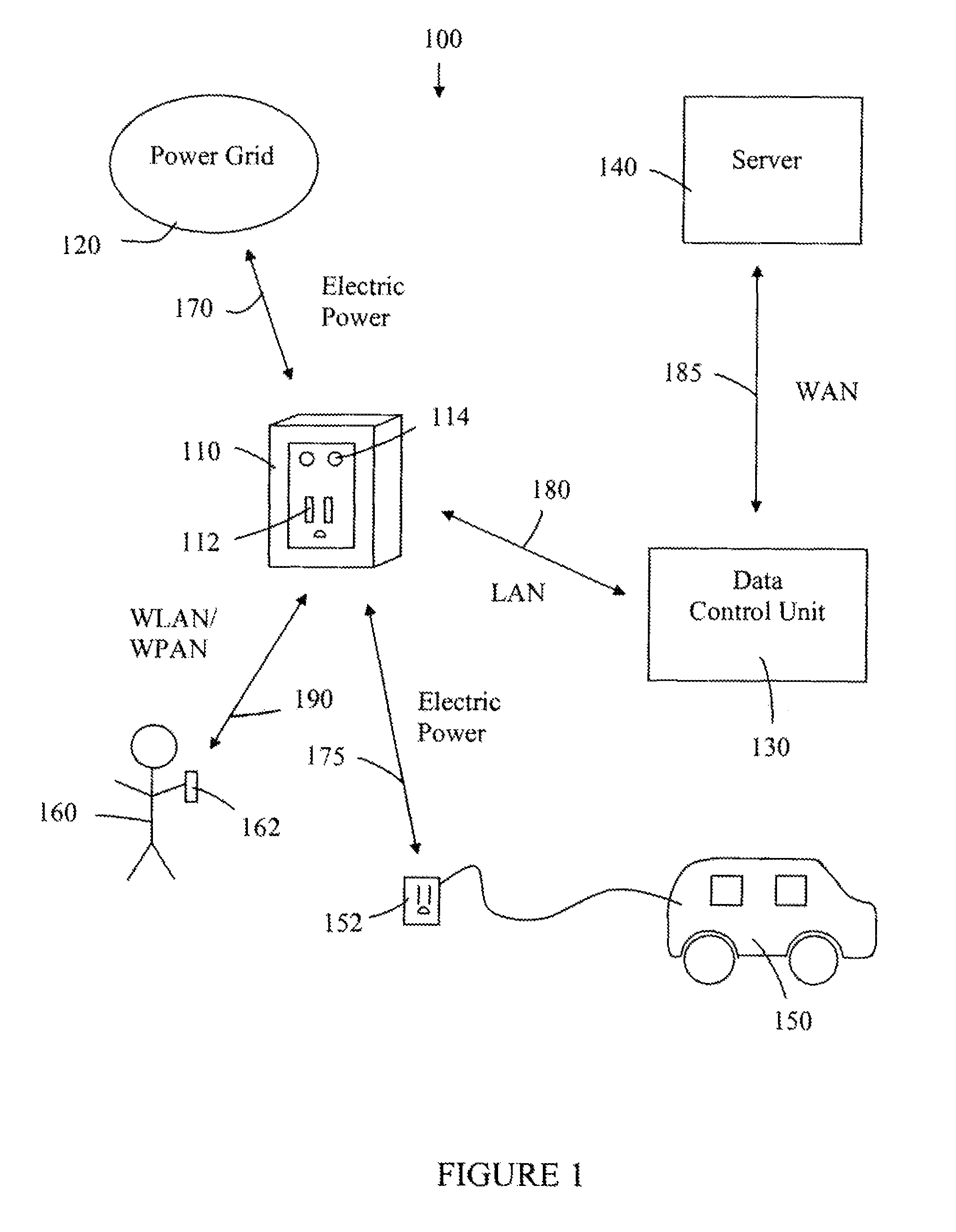
the network-controlled charge transfer system 100 for charging electric vehicles is shown in FIG. 1. The system 100 comprises a network-controlled charge transfer device 110, a local power grid 120, a data control unit 130, and a server 140. The system 100 interfaces with an electric vehicle 150, with an electrical connector 152, and an electric vehicle operator 160, via a mobile communication device 162. The network-controlled charge transfer device 110, referred to herein as a Smartlet™, is connected to the local power grid 120 by an electric power line 170, and to the electric vehicle 150 by the electrical connector 152. The flow of electrical power may be in either direction for both of these electrical connections. In other words, the electric vehicle 150 can be recharged from the local power grid 120, or the local power grid 120 can receive power from the electric vehicle 150. The Smartlet™110 has a communication link to the data control unit 130 over a local area network (LAN...

second embodiment

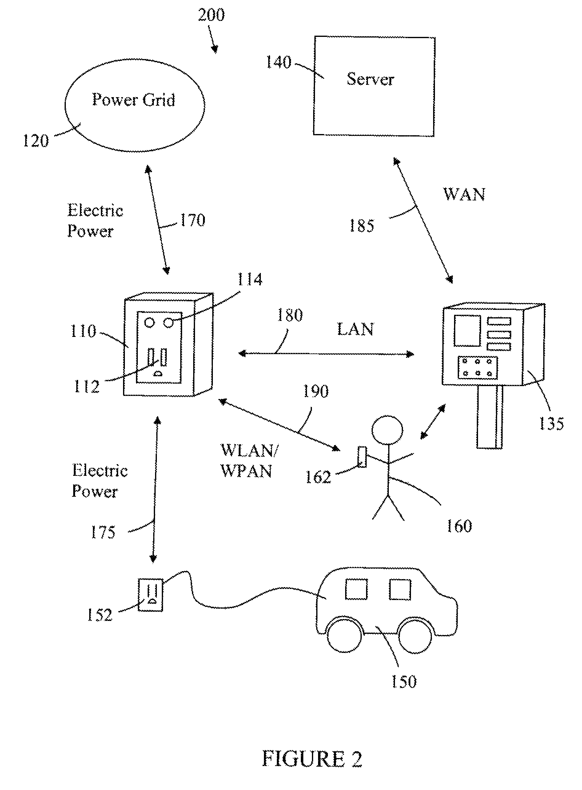
the network controlled charge transfer system 200 for charging electric vehicles 150 is shown in FIG. 2. The system 200 comprises a network-controlled charge transfer device (Smartlet™110, a local power grid 120, a payment station 135, and a server140. The system 200 interfaces with an electric vehicle 150, with an electrical connector 152, and an electric vehicle operator 160, via a mobile communication device 162. The Smartlet™110 is connected to the local power grid 120 by an electric power line 170, and to the electric vehicle 150 by the electrical connector 152. The flow of electrical power may be in either direction for both of these electrical connections. The Smartlet™110 has a communication link to the payment station 135 over a LAN 180. The LAN 180 may be either a WLAN or a PLC network. The payment station 135 has a communication link to the server 140 over a WAN 185. (In this embodiment, the payment station 135 is taking the place of the data control unit 130 for acting a...


PUM

PropertyMeasurementUnit
voltagesaaaaaaaaaa
voltagesaaaaaaaaaa
voltagesaaaaaaaaaa

Abstract

A network-controlled charge transfer device for transferring charge between a local power grid and an electric vehicle is mounted to a street light. The charge transfer device includes the following: an electrical receptacle to receive an electrical connector for connection to the electric vehicle; an electric power line that couples the power grid to the electrical receptacle through a wiring box; a control device to switch the receptacle on and off; a current measuring device to measure current flowing through the electric power line; and a controller to operate the control device and to monitor output from the current measuring device.

Description

BACKGROUND1. FieldThis invention relates to the field of systems and methods for recharging electric vehicles and for providing electricity to consumers and to network controlled electrical outlets used in such systems.2. BackgroundThe electric car, electric vehicle (EV) and battery electric vehicle are all used to describe automobiles powered by one or more electric motors utilizing energy stored in rechargeable batteries. The batteries are recharged by connecting to an electrical outlet. Efficient recharging of the batteries typically requires hours and is often done overnight or while the electric vehicle is parked for a significant time. The use of electric vehicles is limited by the sparse availability of recharging facilities. There is a need for more widespread recharging facilities. Furthermore, there is a need for more recharging facilities available where vehicles are parked for longer periods of time.An important part of any consumer experience is the ease of acquiring a ...

Claims


Application Information

Patent Timeline
Patent Type & Authority Patents(United States)
IPC IPC(8): H01M10/44H01M10/46
CPCG06Q30/04G07C5/008B60L11/1809B60L11/1838B60L11/1816B60L11/1825B60L11/184B60L11/1842B60L11/1844B60L11/1846B60L11/1848G06Q50/06Y02E60/721G07C5/085Y02T10/7005Y02T10/7088Y02T90/14Y02T90/163Y02T90/128Y04S50/12B60L2230/16B60L2230/40Y02T90/169Y02T90/121Y04S10/126Y04S30/14B60L53/14B60L53/00B60L53/31B60L53/64B60L55/00B60L53/63B60L53/65B60L53/665B60L53/305B60L53/68H04B7/26Y02E60/00Y02T10/7072Y02T10/70Y02T90/12Y02T90/167Y02T90/16H02J7/00034H02J7/0042H02J7/04F21S8/086F21V23/001
Inventor LOWENTHAL, RICHARDBAXTER, DAVIDBHADE, HARJINDERMANDAL, PRAVEENTORMEY, MILTON T.
Owner COULOMB TECHNOLOGIES
Why Eureka
Try Eureka