Collection of electric vehicle power consumption tax

a technology for electric vehicles and power consumption, applied in the field of systems and methods for collecting electricity consumption taxes, can solve the problems of low demand, limited use of electric vehicles, and inefficient recharging of batteries that typically requires hours, and achieve accurate measurement and reporting of electricity consumed

Inactive Publication Date: 2009-07-09
COULOMB TECHNOLOGIES
View PDF41 Cites 303 Cited by
  • Summary
  • Abstract
  • Description
  • Claims
  • Application Information

AI Technical Summary

Benefits of technology

[0021]A system for network-controlled charging of electric vehicles and the network-controlled electrical outlets used in this system are described herein. The system comprises electrical outlets, called Smartlets™, networked as follows: Smartlets™ and electric vehicle operators communicate via wireless communication links; Smartlets™ are connected by a LAN to a data control unit; and the data control unit is connected to a server via a WAN. The server stores: consumer profiles (including account information for payment); utility company power grid load data (updated in real time by the utility company); electricity consumption data that may be required for government tax purposes; and tax rate information received from tax authorities to allow an electric vehicle power consumption tax to be calculated. The system may be vehicle-to-grid enabled. The system of the invention may be used to assist in collecting a tax on electricity consumption by electric vehicles—the Smartlet™ system provides accurate measurement and reporting of electricity consumed by electric vehicles.

Problems solved by technology

Efficient recharging of the batteries typically requires hours and is often done overnight or while the electric vehicle is parked for a significant time.
The use of electric vehicles is limited by the sparse availability of recharging facilities.
Conversely, there are periods of low demand which coincide with high electricity production.
Should electric vehicles start to replace significant numbers of gasoline burning vehicles there will be a drop in tax revenues.
This technology is restricted to short distances for high-speed transmission of large amounts of data.

Method used


Image

  • Collection of electric vehicle power consumption tax
  • Collection of electric vehicle power consumption tax
  • Collection of electric vehicle power consumption tax

Examples


first embodiment

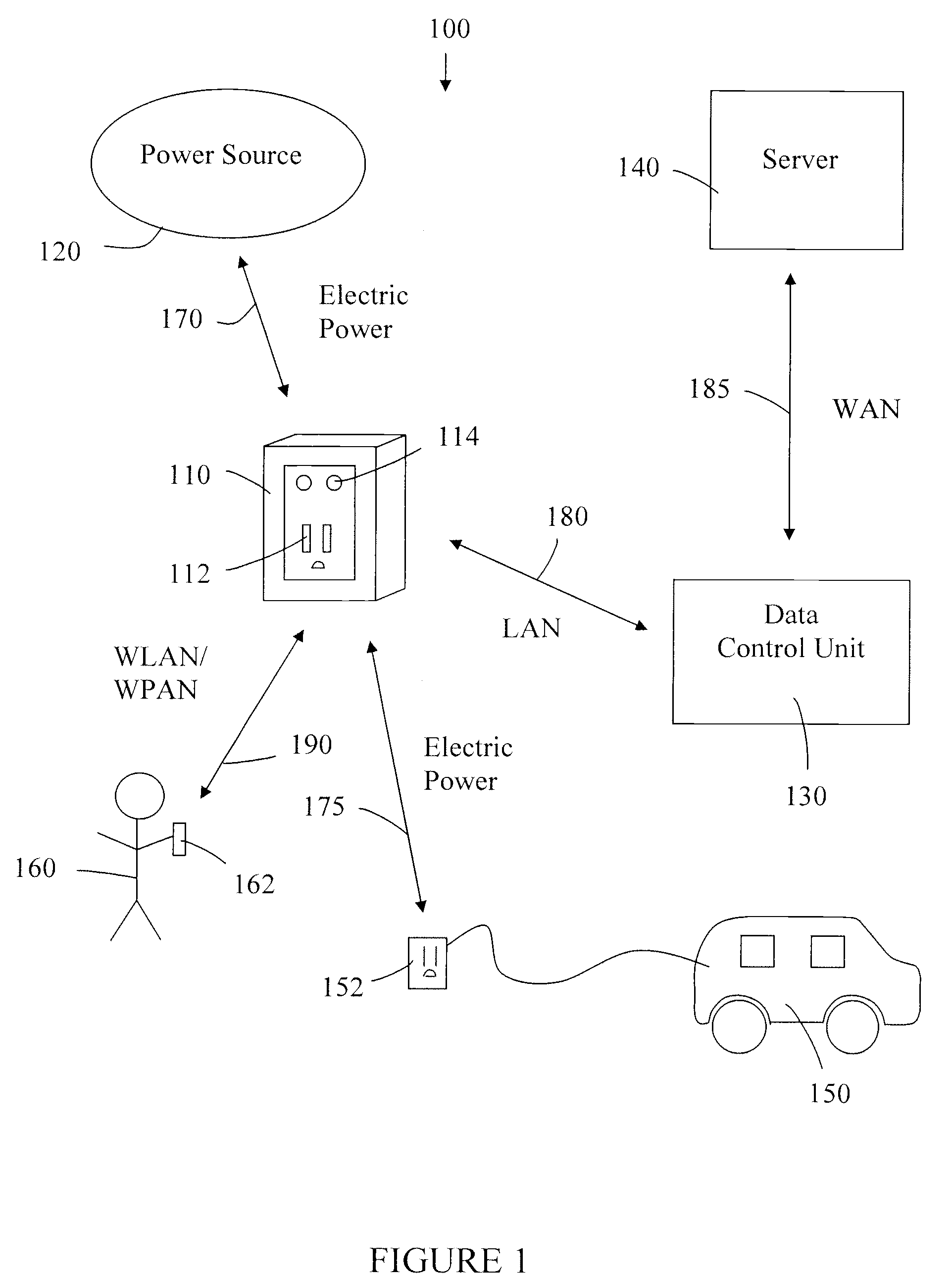
[0035]the network-controlled charge transfer system 100 for charging electric vehicles is shown in FIG. 1. The system 100 comprises a network-controlled charge transfer device 110, a local power source 120, a data control unit 130, and a server 140. The system 100 interfaces with an electric vehicle 150, with an electrical connector 152, and an electric vehicle operator 160, via a mobile communication device 162. The network-controlled charge transfer device 110, referred to herein as a Smartlet™, is connected to the local power source 120 by an electric power line 170, and to the electric vehicle 150 by an electrical cable 175. As shown in FIG. 1, the electric vehicle 150 may be connected to the Smartlet™110 by an electrical connector 152 provided by the electric vehicle operator 160. Alternatively, as shown in FIG. 2, the electric vehicle may be connected to the Smartlet 110 by an electrical cable 116 which is hard wired into the Smartlet™110. The flow of electrical power may be i...

second embodiment

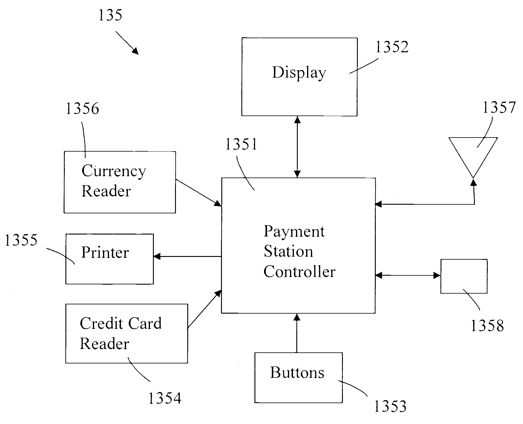
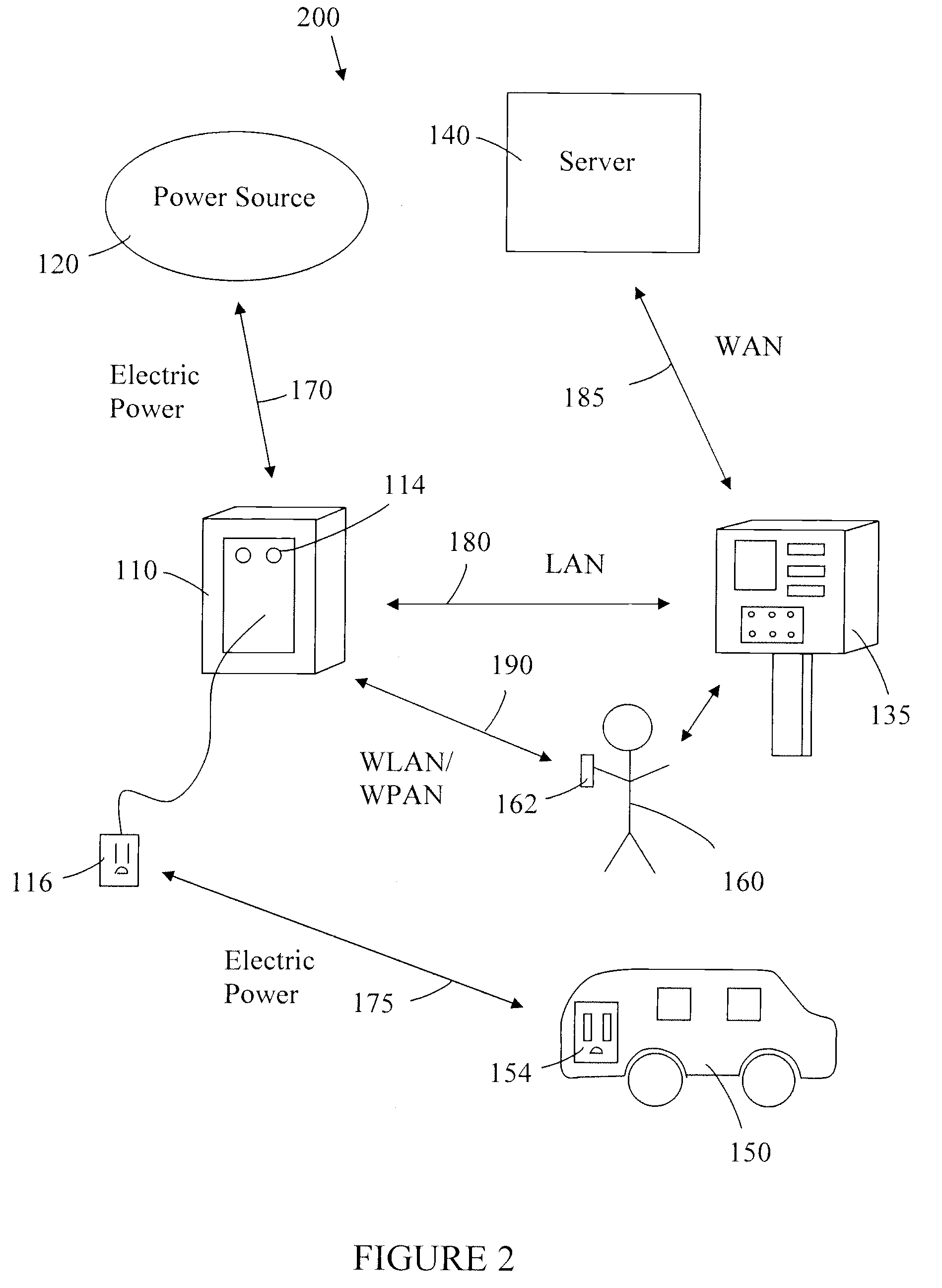
[0043]the network controlled charge transfer system 200 for charging electric vehicles 150 is shown in FIG. 2. The system 200 comprises a network-controlled charge transfer device (Smartlet™) 110, a local power source 120, a payment station 135, and a server 140. The system 200 may be interfaced with an electric vehicle 150, with an electrical cable 116, and an electric vehicle operator 160, via a mobile communication device 162. (In alternative embodiments, the electric vehicle may be connected to the system 200 by an electrical connector 152. See FIG. 1 for an example of such a connection.) The Smartlet™110 is connected to the local power source 120 by an electric power line 170, and to the electric vehicle 150 by the electrical cable 116. The electric vehicle 150 has a vehicle receptacle 154 for connecting with electrical cable 116. In some embodiments, an electric meter may be positioned between the Smartlet™110 and the power line 170. The flow of electrical power may be in eith...


PUM


Abstract

A method of collecting electric vehicle power consumption tax for charge transferred between a local power source and an electric vehicle comprises: providing a network-controlled charge transfer device, charge transfer being controlled by a controller, the controller being connected to a network for communication to a server; requesting by an operator of the electric vehicle to the controller for charge transfer; relaying the request from the controller to the server; determining by the server, from geographical tax rate data and the geographical location of the network-controlled charge transfer device, an applicable tax rate on the charge transfer; enabling charge transfer by communicating from the server to the controller to activate the control device; monitoring the charge transfer using a current measuring device, the controller being configured to monitor the output from the current measuring device and to maintain a running total of charge transferred; detecting completion of the charge transfer; and on detecting completion, processing payment with said payment source, which may include deducting the cost of charge transfer from a subscriber account containing pre-transferred funds, and disabling charge transfer; wherein the request for payment includes the electric vehicle power consumption tax.

Description

CROSS-REFERENCE TO RELATED APPLICATIONS[0001]This application claims the benefit of U.S. Provisional Application Ser. No. 61 / 081,333, filed Jul. 16, 2008 and U.S. Provisional Application Ser. No. 61 / 019,474, filed Jan. 7, 2008, which are expressly incorporated by reference herein.BACKGROUND OF THE INVENTION[0002]1. Field of the Invention[0003]This invention relates to the field of systems and methods for collecting an electricity consumption tax for electric vehicles.[0004]2. Description of the Related Art[0005]The electric car, electric vehicle (EV) and battery electric vehicle are all used to describe automobiles powered by one or more electric motors utilizing energy stored in rechargeable batteries. The batteries are recharged by connecting to an electrical outlet. Efficient recharging of the batteries typically requires hours and is often done overnight or while the electric vehicle is parked for a significant time. The use of electric vehicles is limited by the sparse availabi...

Claims


Application Information

Patent Timeline
Patent Type & Authority Applications(United States)
IPC IPC(8): G06Q20/00
CPCB60L11/1824Y04S50/12B60L11/1846B60L11/1848B60L2240/627G06Q20/10G06Q20/127G06Q20/18G06Q20/32G06Q20/3224G06Q20/325G06Q20/3278G07F15/005G07F15/08G07F17/0014G07F17/246Y02T10/7005Y02T10/7291Y02T90/128Y02T90/14Y02T90/16Y02T90/162Y02T90/163Y02T90/169Y04S30/14B60L11/1816Y02T90/121B60L11/184B60L53/14B60L53/64B60L53/65B60L53/665B60L53/68B60L53/305Y02T10/7072Y02T10/72Y02T90/12Y02T90/167Y02T10/70
Inventor LOWENTHAL, RICHARD W.BAXTER, DAVEBHADE, HARJINDERMANDAL, PRAVEEN
Owner COULOMB TECHNOLOGIES
Why Eureka
Try Eureka