Vibrating microtome with automated measurement of vertical runout

a microtome and vertical runout technology, applied in the direction of saw chains, paper/cardboard containers, instruments, etc., can solve the problems of time-consuming and cumbersome operation of aligning knife edges, the knife edge does not move exactly parallel, etc., to simplify and speed up the alignment of knives

Active Publication Date: 2011-06-07
LEICA BIOSYST NUSSLOCH
View PDF26 Cites 3 Cited by
  • Summary
  • Abstract
  • Description
  • Claims
  • Application Information

AI Technical Summary

Benefits of technology

[0005]It is therefore an object of the invention to indicate a way to simplify and speed up alignment of the knife in terms of vertical runout, and to configure said alignment reliably for the entire range of possible vibration amplitudes and frequencies of the knife.
[0007]As a result of this manner according to the present invention of achieving the object, which provides for the use of a constant-phase signal to define the measurement points in time, the accuracy and repeatability of the measurement of the transverse offset (vertical runout) can be substantially increased. It is furthermore easier, or indeed possible at all, to eliminate interfering influences.
[0010]The measuring device, especially when it is realized as a detachable unit, can favorably generate a signal that describes the magnitude of the measured transverse offset, and convey said signal to the vibrating microtome so that it can be displayed, for example, on a display associated with the vibrating microtome.
[0012]It is furthermore advantageous, in order to preclude interfering influences, if the electronic measurement system is additionally configured to adjust the intensity of the light beam of the light barrier prior to a determination of the transverse offset, namely with the cutting edge in a position completely outside the light barrier, wherein a utilization exceeding 90%, e.g. 95%, of the modulation range of the detector element of the light barrier is established.

Problems solved by technology

Because of the tolerances of the knife holder and knife, however, it is inevitable that the knife edge does not move exactly parallel to the vibration direction.
This operation of aligning the knife edge is time-consuming and cumbersome, not least because pivoting of the knife is generally associated with a realignment of the Z position.

Method used


Image

  • Vibrating microtome with automated measurement of vertical runout
  • Vibrating microtome with automated measurement of vertical runout
  • Vibrating microtome with automated measurement of vertical runout

Examples


Embodiment Construction

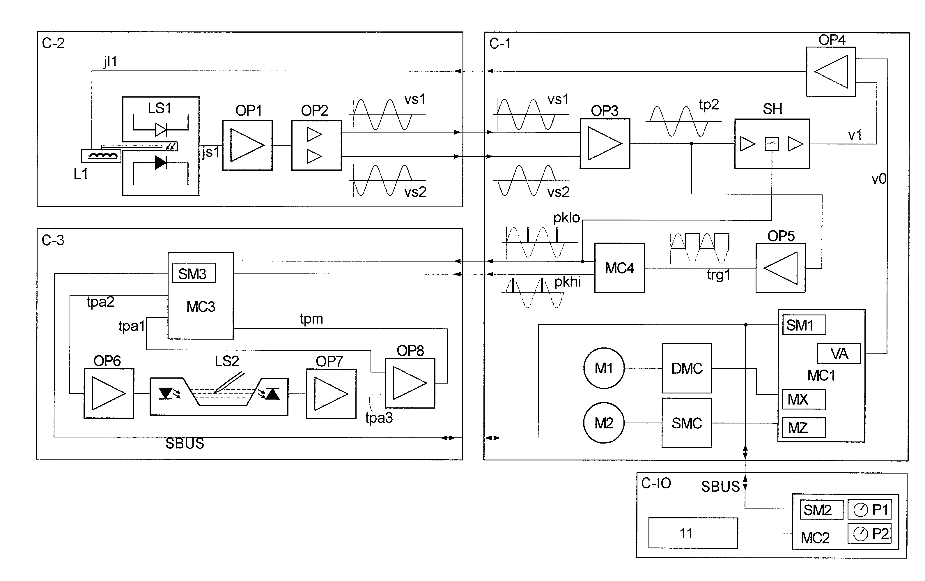
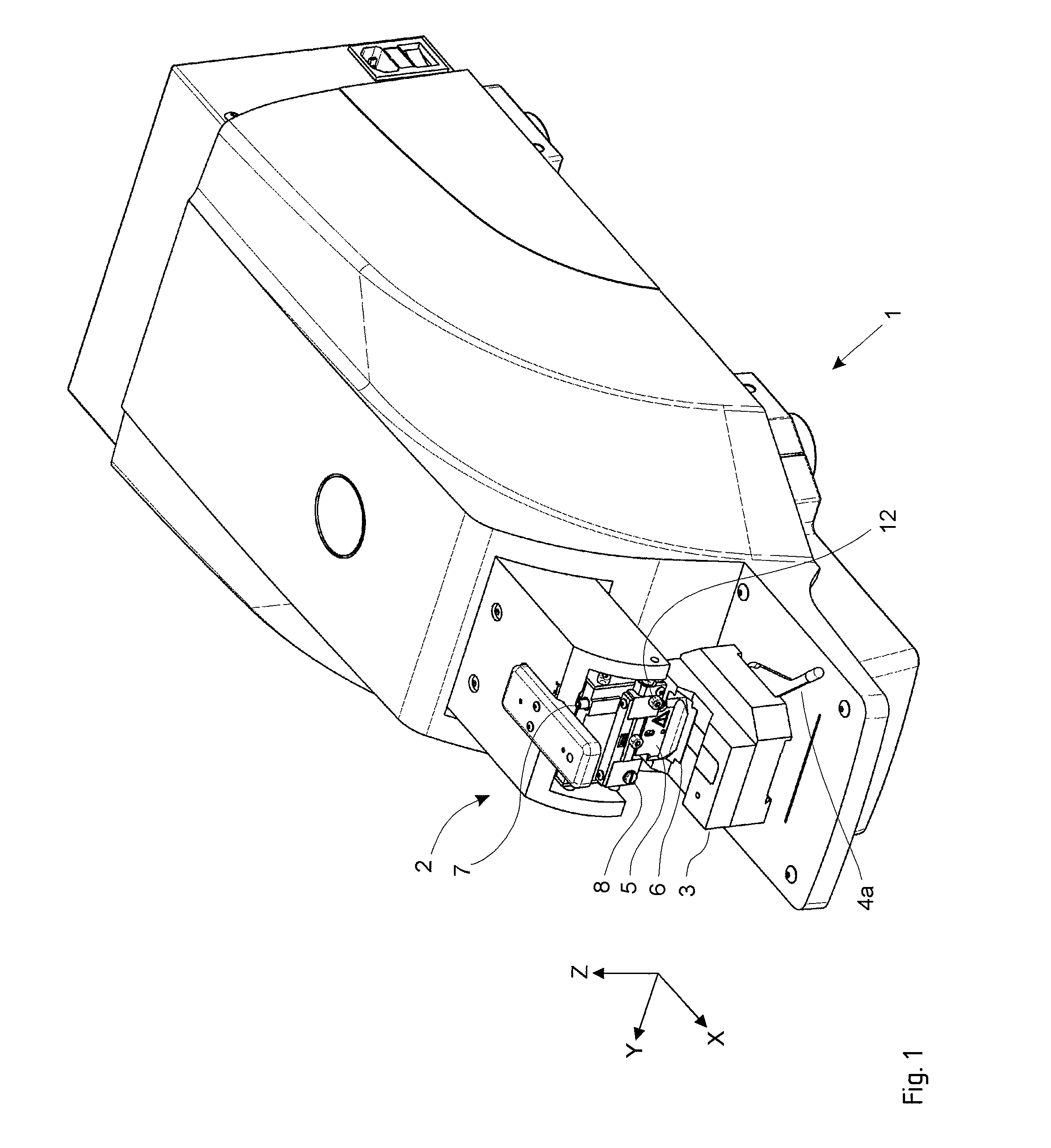
[0020]The exemplifying embodiment presented below relates to a vibrating microtome in which a vertical runout measuring device in the form of a measuring head is installed instead of the sample holder. A determination of the linear modulation range of the detector element is carried out on the part of the measuring head, in the lowered position, at the beginning of each measurement, and the intensity of the light barrier of the transmitting element is set in such a way that the (uncovered) detector element is operated close to the upper limit of its linear modulation range. The measurement itself is performed in the middle of the linear modulation range, typically at 50% occlusion by the knife. The result of this operation is that each measurement operation is individually calibrated and remains largely independent of long-term interfering influences (temperature, extraneous light, component drift).

[0021]The measuring head as a whole does not require any adjusting element that would...


PUM

PropertyMeasurementUnit
vibration frequencyaaaaaaaaaa
plastic stabilityaaaaaaaaaa

Abstract

A vibrating microtome and measuring device for measuring the transverse offset of a vibrating knife comprises a light barrier into which the knife is placeable and a control application signal (pklo, pkhi) that describes the time course of the vibration of the knife and an electronic measurement system of the measuring device measures the coverage of the light barrier as an oscillating signal (tpm), and determines the transverse offset from the signal values at points in time that are defined by the control application signal.

Description

CROSS REFERENCE TO RELATED APPLICATIONS[0001]This application claims priority of German patent application 10 2006 041 208.7 filed Sep. 2, 2006, which is incorporated by reference herein.FIELD OF THE INVENTION[0002]The present invention relates to a device for measuring the vertical runout in a vibrating microtome. More precisely, the invention relates to a vibrating microtome in which a knife is configured, in particular during a sectioning operation, to vibrate in a direction parallel to a section plane and substantially (i.e. within alignment accuracy values) parallel to a cutting edge of the knife, and to a pertinent measuring device that, for measurement of the transverse offset of the cutting edge in the context of its lateral vibratory motion as a consequence of a potentially present inclination of the cutting edge with respect to the section plane, comprises a light barrier into which the cutting edge is placeable, the light barrier being oriented in a direction parallel to ...

Claims


Application Information

Patent Timeline
Patent Type & Authority Patents(United States)
IPC IPC(8): B26D1/00
CPCG01B11/2408G01N1/06G01N2001/065Y10T83/0333Y10T83/141Y10T83/148Y10T83/929B23Q17/24G01B11/272G01V8/12
Inventor TANKI, SIEGFRIEDREDL, FELIX
Owner LEICA BIOSYST NUSSLOCH
Why Eureka
Try Eureka