Cutting segment for cutting tool and cutting tools

a cutting tool and cutting tool technology, applied in the field of cutting segments, can solve the problems of lowering the cutting rate, diamond particles are not uniformly distributed, and the cutting rate is contradictory to its useful life, so as to improve the cutting rate and the useful life

Active Publication Date: 2011-06-07
NIWA DAIYAMONDO INDS +1
View PDF39 Cites 14 Cited by
  • Summary
  • Abstract
  • Description
  • Claims
  • Application Information

AI Technical Summary

Benefits of technology

[0024]The present invention has been made to solve the foregoing problems of the prior art and therefore an object according to certain embodiments of the present invention is to provide a cutting segment improved in cutting rate and useful life by adjusting the thickness of a blank section with no abrasive particles, and a cutting tool having the cutting segment.Technical Solution
[0046]The thick blank sections successively arranged weakens a power to retain the abrasive particles owing to more abrasion of metal powder, thereby causing the cutting segment to be rapidly worn away. Meanwhile, four or more of the thin blank sections successively arranged reduces protrusion height of the abrasive particles due to too shallow grooves in the thin blank sections, consequently deteriorating cutting rate.
[0047]Preferably, the thick blank sections each have a thickness of 0.75 to 2 times the average diameter of the abrasive particles. The thickness less than 0.75 times the average diameter of the abrasive particles excessively shallows grooves caused by abrasion, lowering protrusion height of the abrasive particle rows and thus diminishing cutting rate. In addition, the thickness more than 2 times excessively deepens the grooves resulting from abrasion, thereby potentially degrading useful life and stability of the cutting segment.

Problems solved by technology

In the cutting tool having the cutting segment, its cutting rate is contradictory to its useful life.
In contrast, in case of using the metal powder with high abrasion resistance to extend useful life, the diamond particles blunted during cutting do not easily fall off, thus lowering cutting rate.
In addition, in case of mixing the diamond particles with the metal powder serving as a bond as just described, the diamond particles are not uniformly dispersed owing to differences between metal powders and diamond particles in terms of particle size and specific gravities.
Therefore, as shown in FIG. 1, this disadvantageously leads to a cutting surface 3 having too many diamond particles or a cutting surface 4 having too few diamond particles, causing the diamond particles to segregate.
Also, cutting rate can be boosted through a special concept of a “shoveling effect.” However, due to the diamond particle rows equally spaced apart from each other, with increase in the depth h of the groove, the metal powder cannot sufficiently retain the diamond particles 25 so that the diamond particles are easily discharged during cutting.
This disadvantageously reduces useful life, especially for a work piece cut into large debris.

Method used


Image

  • Cutting segment for cutting tool and cutting tools
  • Cutting segment for cutting tool and cutting tools
  • Cutting segment for cutting tool and cutting tools

Examples


example 1

[0127]One saw blade was manufactured according to the invention (Inventive product 1) and two saw blades were manufactured according to the prior art (Conventional products 1 and 2). The inventive and conventional saw blades were used to examine cutting rate and useful life of cutting segments in order to cut a granite work piece. The results are shown in Table 1.

[0128]Also, abrasion shapes of the cutting segments were observed.

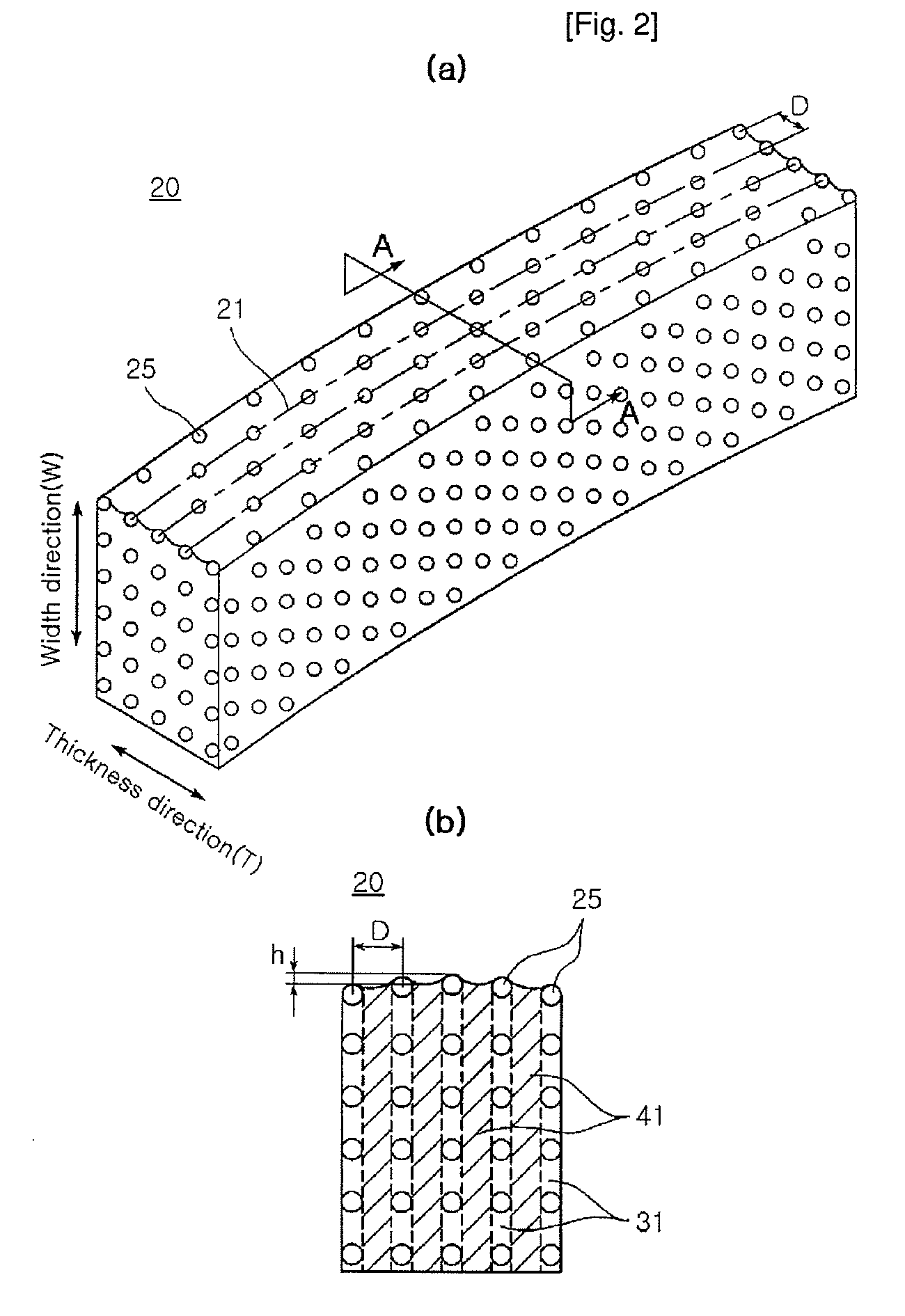
[0129]Herein, Inventive product 1 used diamond particles as abrasive particles. The segments each had a length L of 40 mm, thickness T of 3.2 mm, width W of 10.0 mm, diameter R of 168 mm, and average diamond concentration of 0.8Conc. The diamond particles used were MBS-955 available from D.I corp. of U.S.A., with a particle size of US 40 / 50 mesh and an average diameter of 400.

[0130]FIG. 15 (a) illustrates shapes of cutting segments in Inventive product 1 according to this embodiment.

[0131]In Inventive product 1, diamond particles were arranged in six rows par...

example 2

[0142]In this Example, cutting segments shaped as in FIGS. 15 (b) to (f) were manufactured after varying a total number of diamond particle layers (rows on a cutting surface), number and thickness of thin blank sections, ratio of thin blank sections and diamond particle size, number and thickness of thick blank sections, ratio of thick blank sections and diamond particle size, thickness ratio of thick blank section and thin blank section, as shown in FIG. 2. Cutting rate and useful life of the cutting segments were observed and the results are shown in Table 3 below.

[0143]The shape of samples 1 and 2 of Table 2 is depicted in FIG. 15 (b), that of samples 3, 4 and 5 is depicted in FIG. 15 (c), that of samples 6 and 7 is depicted in FIG. 15 (d), and that of sample 9 is depicted in FIG. 15 (f).

[0144]Cutting rate and useful life of samples shown in Table 3 are comparative values when the conventional products having diamond particles randomly dispersed therein are assumed to have a valu...

example 3

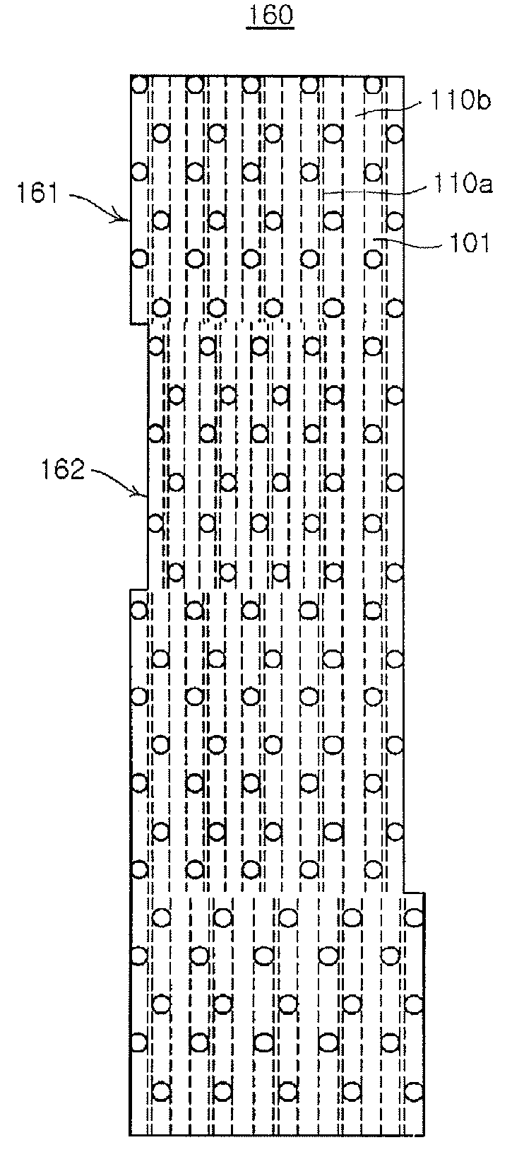
[0159]24-inch saw blades (samples 10 and 11) were prepared by welding cutting segments to an outer peripheral surface of a metal core, in which the cutting segments had thick blank sections and thin blank sections or had thick blank sections and non-blank sections.

[0160]Sample 10 was a cutting tool only comprised of one type of cutting segments each having the thick blank sections and thin blank sections disposed therein, out of the cutting segment types according to the invention.

[0161]Sample 11 was a cutting tool having both types of cutting segments alternately welded, out of the cutting segment segments according to the invention. Herein, all the cutting segments included the thick blank sections and non-blank sections, but in the cutting segments, the non-blank sections of a trailing cutting segment were disposed in the thick blank sections of a leading cutting segment.

[0162]FIG. 16 (a) illustrates a cross-section of cutting segments used in Sample 10. FIG. 16 (b) illustrates a...


PUM

PropertyMeasurementUnit
widthaaaaaaaaaa
diameteraaaaaaaaaa
widthaaaaaaaaaa

Abstract

The invention provides a cutting segment for a cutting tool for cutting or drilling a brittle work piece such as stone, bricks, concrete and asphalt, and a cutting tool having the cutting segment. The cutting segment includes a cutting surface for cutting a work piece and a plurality of abrasive particle layers. The abrasive particle layers are disposed perpendicular to a cutting direction. Each of the abrasive layers has a plurality of abrasive particle rows in a width direction of the cutting segment. Each of the abrasive rows has a plurality of abrasive particles arranged in a line. Further, the abrasive layers have a plurality of blank sections therebetween. In the blanks sections, abrasive particles are absent or have a concentration of 70% or less with respect to those in the abrasive rows. In addition, the blank sections include relatively thick blank sections and relatively thin blank sections.

Description

CROSS-REFERENCE TO RELATED APPLICATIONS[0001]This application is a National Stage application of International Application No. PCT / KR2006 / 001442, with an international filing date of Apr. 19, 2006 based on Korean Patent Application No. 2005-33340 filed on Apr. 21, 2005 and Korean Patent Application No. 2006-21939 filed on Mar. 8, 2006.TECHNICAL FIELD[0002]The present invention relates to a cutting segment for a cutting tool for cutting or drilling a brittle work piece such as stone, bricks, concrete and asphalt, and a cutting tool having the cutting segment. More particularly, the present invention relates to a cutting segment improved in cutting rate and useful life by properly arranging abrasive particles, and a cutting tool having the cutting segment.BACKGROUND ART[0003]To cut or drill a brittle work piece such as stone, bricks, concrete and asphalt requires abrasive particles having higher hardness than a work piece.[0004]The abrasive particles are exemplified by artificial diam...

Claims


Application Information

Patent Timeline
Patent Type & Authority Patents(United States)
IPC IPC(8): B28D1/12
CPCB24D5/123B28D1/121B27B33/02B24D99/005
Inventor KIM, SOO-KWANGPARK, HEE-DONGCHANG, JOON-HOKIM, JONG-HO
Owner NIWA DAIYAMONDO INDS
Why Eureka
Try Eureka