Turnlock fastener

a technology of turnlock and fastener, which is applied in the direction of rod connection, sheet joining, ropes and cables for vehicles/pulleys, etc., can solve the problem of relative high pullout force and achieve the effect of large pullout for

Active Publication Date: 2011-06-07
A RAYMOND & CO
View PDF4 Cites 29 Cited by
  • Summary
  • Abstract
  • Description
  • Claims
  • Application Information

AI Technical Summary

Benefits of technology

[0008]The present invention provides a turnlock fastener that can be secured in advance within certain relatively large dimensions of insertion openings of different sizes and with relatively large pullout forces.
[0009]Since the preliminary securing arrangement in the turnlock fastener according to the invention has radially elastic spring limbs, the turnlock fastener according to the invention can be placed in insertion openings with a relatively wide range of dimensions or relatively large tolerances and can be arranged in a pre-secured position in which the spring limbs grip the edge of the insertion opening from behind. This gripping from behind also results in a relatively high pullout force, since a very strong obstruction is created, preventing axial movement against the direction of insertion, due to the outward elasticity of the spring limbs after entering the insertion opening.
[0010]In one form thereof, the present invention provides a turnlock fastener to connect two components having a cover plate, with a base shaft molded onto the cover plate and extending away from the cover plate, on which, at a distance from the cover plate, at least two rigid locking stands sitting opposite one another and extending radially outward from the base shaft are placed, and with a fixing arrangement to secure the turnlock fastener to a first component, the fixing arrangement having at least two radially elastic spring limbs, each of which is arranged circumferentially between two locking stands and with one end connected with the base shaft and extending with the other, free end away from the base shaft toward the cover plate, characterized in that the spring limbs are arranged such that they grip from behind an insertion opening fashioned in a first component, that the locking stands each exhibit a starting bevel sitting on the front in the direction of rotation and that a surrounding sealing lip of a soft elastic material is placed on the side of the cover plate facing the base shaft, the distance between the contact sides of the locking stands facing the cover plate and the front side of the sealing lip facing away from the cover plate being arranged such that the sealing lip is deformed in a final fixing arrangement to achieve a sealing effect.

Problems solved by technology

This gripping from behind also results in a relatively high pullout force, since a very strong obstruction is created, preventing axial movement against the direction of insertion, due to the outward elasticity of the spring limbs after entering the insertion opening.

Method used


Image

  • Turnlock fastener
  • Turnlock fastener
  • Turnlock fastener

Examples


Embodiment Construction

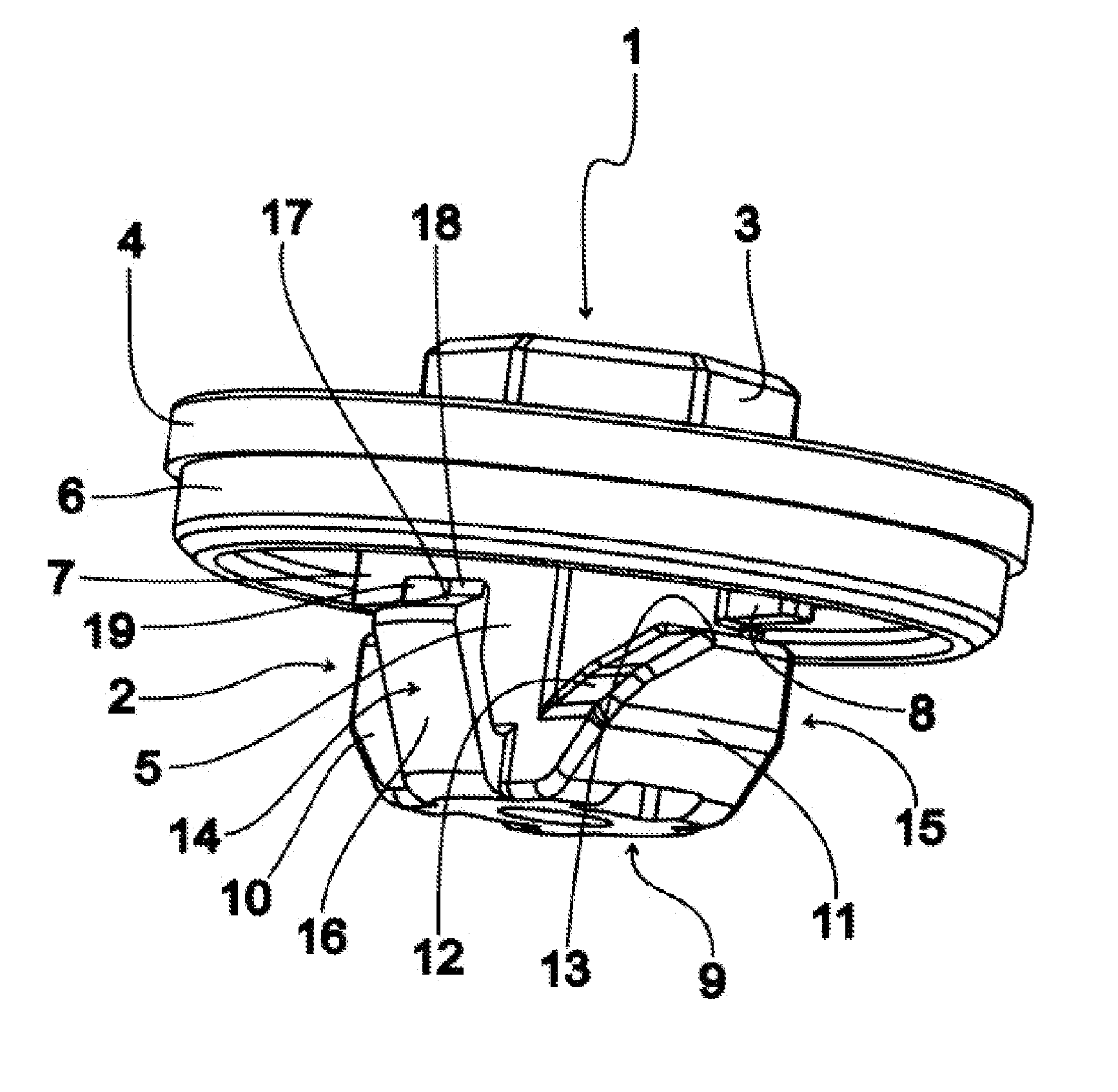
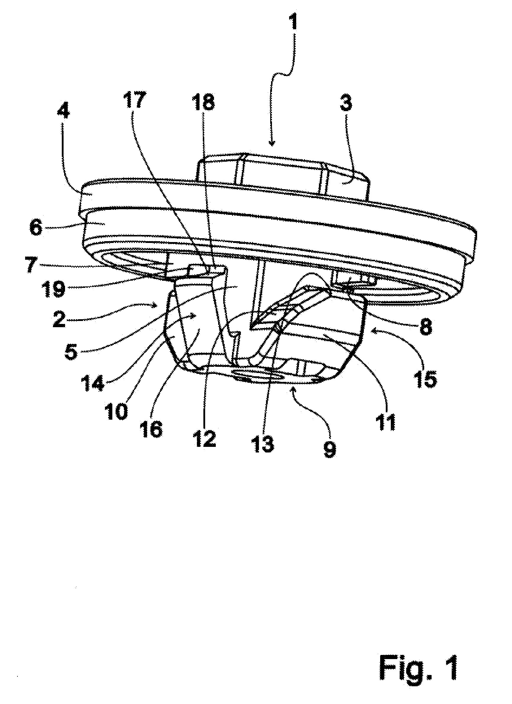
[0020]FIG. 1 shows a perspective view of an exemplary embodiment of a turnlock fastener 1 according to the invention. The exemplary turnlock fastener 1 has a base body 2 made of a hard elastic plastic material, in this exemplary embodiment having a hex head 3 as a tool catch structure, a disc-like cover plate 4 connected with the hex head 3 and extending radially beyond it and a base shaft 5 molded onto the side of the cover plate 4 located opposite the hex head 3 and extending away from the cover plate 4 in the axial direction.

[0021]Furthermore, the turnlock fastener 1 is equipped with a sealing lip 6 of a soft elastic material arranged along the outer edge of the cover plate 4 on the side of the base shaft 5 and connected with the cover plate 4.

[0022]In the neck area of the base shaft 5, elongated stop crosspieces 7, 8 are formed on the cover plate 4, arranged on both sides of the base shaft 5, extending radially away from the base shaft 5. Massive locking stands 10, 11 are molded...


PUM


Abstract

A turnlock fastener (1) for the connection of two components features a cover plate (4) and a base shaft (5) which is formed on the cover plate (4) and which extends away from the cover plate (4), at which at least two opposing rigid locking stands (10, 11) are positioned at a distance from the cover plate (4) and extend outward from the base shaft (5) in the radial direction. In addition, a fixing arrangement is provided to secure the turnlock fastener (1) to a first component which possesses at least two radial elastic spring limbs (14, 15) which are each arranged between two locking stands (10, 11) and which are connected at one end with the base shaft (5) and which extend away from the base shaft (5) with the other free end in the direction of the cover plate (4). That way, the turnlock fastener (1) can be secured ahead of time within certain relatively large dimensions of insertion openings of different sizes and with relatively large pullout forces.

Description

CROSS-REFERENCE TO RELATED APPLICATION[0001]This application is a U.S. National Phase Patent Application based on International Application Serial No. PCT / EP2007 / 003089 filed Apr. 5, 2007, the disclosure of which is hereby explicitly incorporated by reference herein.BACKGROUND OF THE INVENTION[0002]1. Field of the Invention[0003]The present invention relates to a turnlock fastener.[0004]2. Description of the Related Art[0005]One turnlock fastener is known from DE 198 38 560 A1. The known turnlock fastener for the connection of two components has a cover plate and a base piece molded to the cover plate. The base piece has a base shaft extending away from the cover plate, on which two opposing rigid locking arms are positioned at a distance from the cover plate and extend radially outward from the base shaft. Furthermore, a preliminary securing arrangement is provided in order to secure the turnlock fastener to a component.[0006]In the known turnlock fastener, the preliminary securing...

Claims


Application Information

Patent Timeline
Patent Type & Authority Patents(United States)
IPC IPC(8): F16B21/00
CPCF16B19/008F16B21/02Y10T403/5793Y10T24/4578F16B5/06F16B5/00
Inventor SILBEREISEN, FRIEDRICHVOLLMER, JURGEN
Owner A RAYMOND & CO
Why Eureka
Try Eureka