Piezoelectric vibration element, manufacturing method for piezoelectric vibration element, piezoelectric resonator, electronic device, and electronic apparatus

a manufacturing method and piezoelectric technology, applied in the direction of piezoelectric/electrostrictive transducers, generators/motors, transducer types, etc., can solve the problems of deterioration of electric characteristics, frequency aging failure, and damage to the cutting surface, and achieve excellent frequency stability, satisfactory s/n ratio, and high frequency

Active Publication Date: 2012-12-06
SEIKO EPSON CORP
View PDF4 Cites 40 Cited by
  • Summary
  • Abstract
  • Description
  • Claims
  • Application Information

AI Technical Summary

Benefits of technology

[0024]A high-frequency fundamental wave piezoelectric vibration element is reduced in size and the spread of stress due to bonding and fixing can be suppressed. Therefore, there is an effect that it is possible to obtain a piezoelectric vibration element excellent in a frequency-temperature characteristic, a CI temperature characteristic, and a frequency aging characteristic and having a small CI value of main vibration and a large ratio of a CI value of near spurious vibrations to the CI value of the main vibration, i.e., a large CI value ratio.Application Example 2
[0042]A high-frequency fundamental wave piezoelectric resonator is reduced in size and the spread of stress due to bonding and fixing can be suppressed. Therefore, there is an effect that it is possible to obtain a piezoelectric resonator excellent in frequency reproducibility, a frequency-temperature characteristic, a CI temperature characteristic, and a frequency aging characteristic. Further, there is an effect that it is possible to obtain a piezoelectric resonator having a small CI value of main vibration and a large ratio of a CI value of near spurious vibrations to the CI value of the main vibration, i.e., a large CI value ratio and having a small capacity ratio.Application Example 11
[0050]By using the piezoelectric resonator in the electronic apparatus, there is an effect that it is possible to configure an electronic apparatus including a reference frequency source having a high frequency, excellent in frequency stability, and having a satisfactory S / N ratio.

Problems solved by technology

Therefore, a cut surface is subject to damage such as chipping and crack and an extremely thin section is broken.
In a vibration region, for example, an unnecessary vibration occurs and a CI value increases, which cause spurious vibrations.
When a reduction in the size of a piezoelectric resonator is realized, deterioration in an electric characteristic and a frequency aging failure are caused by residual stress due to an adhesive.
However, it has been found that, in the piezoelectric resonators having the structures explained above, a CI value of main vibration, a near spurious CI value ratio (=CIs / CIm, where CIm is the CI value of the main vibration and CIs is a CI value of spurious vibrations; the near spurious CI value ratio is equal to or larger than 1.8 in one example of a standard), and the like cannot satisfy requirements.

Method used


Image

  • Piezoelectric vibration element, manufacturing method for piezoelectric vibration element, piezoelectric resonator, electronic device, and electronic apparatus
  • Piezoelectric vibration element, manufacturing method for piezoelectric vibration element, piezoelectric resonator, electronic device, and electronic apparatus
  • Piezoelectric vibration element, manufacturing method for piezoelectric vibration element, piezoelectric resonator, electronic device, and electronic apparatus

Examples


first embodiment

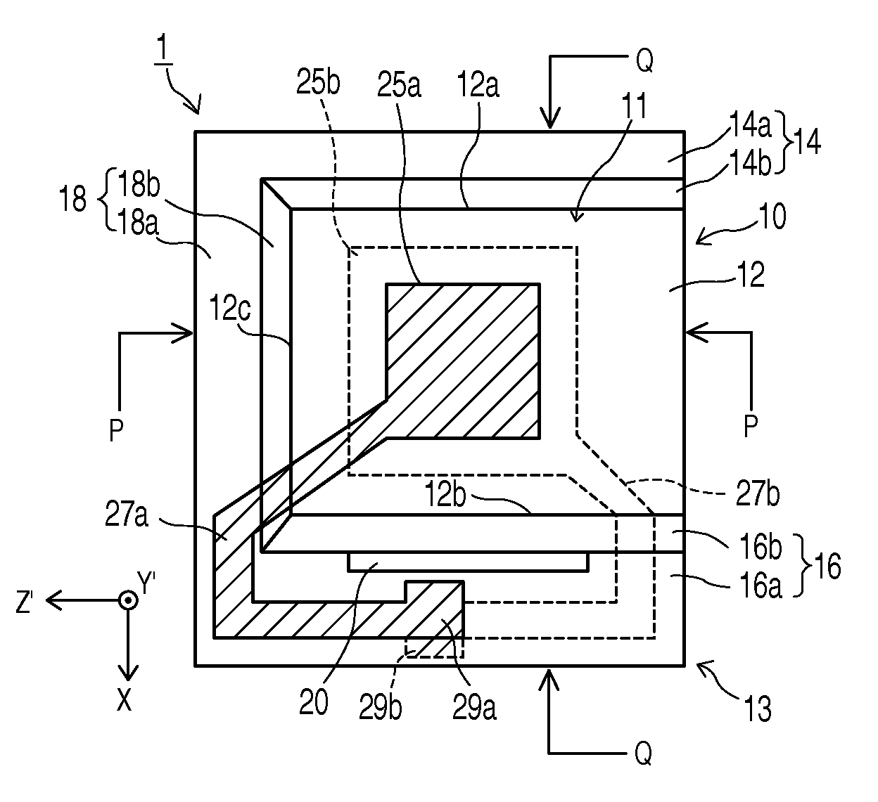
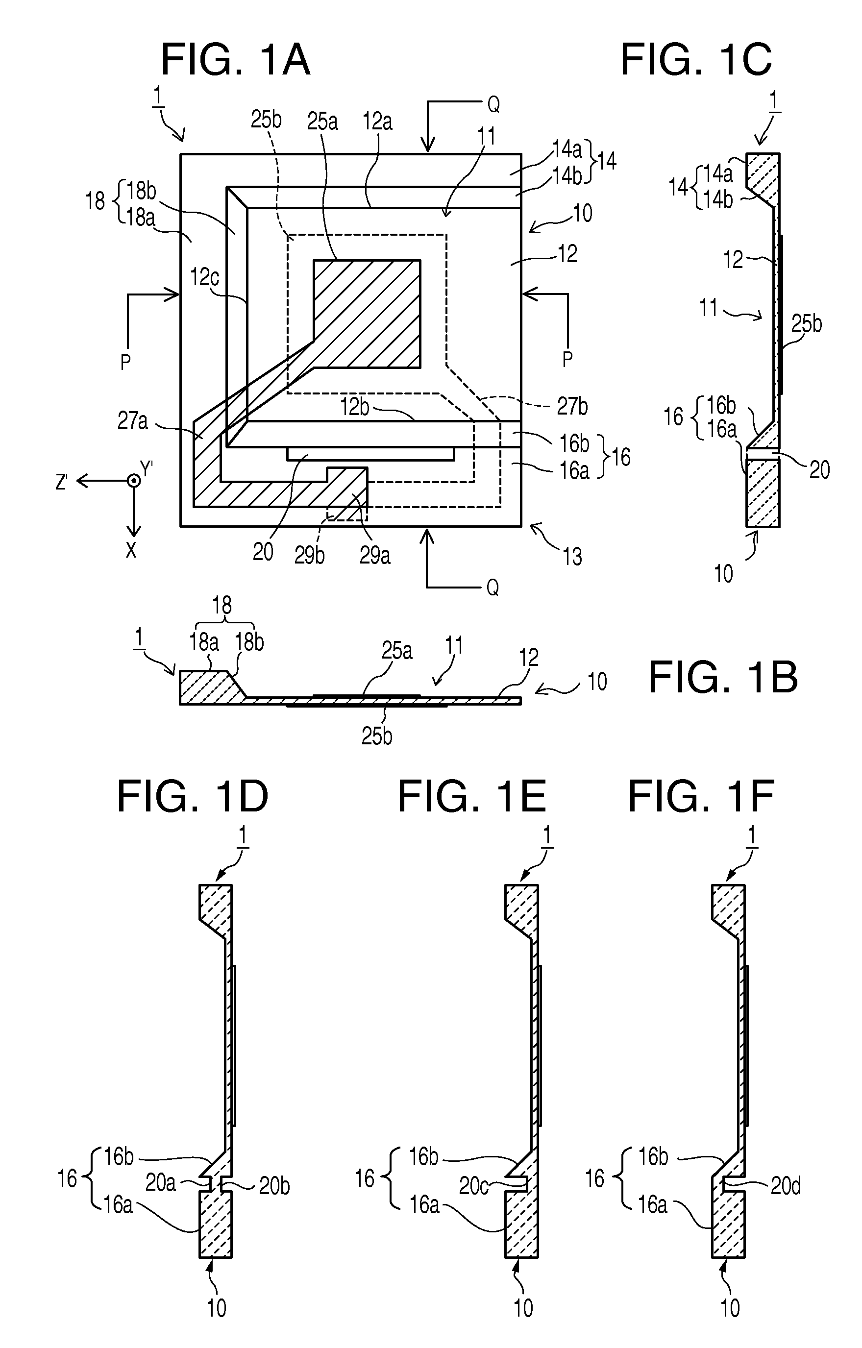
[0075]Embodiments of the invention are explained in detail below with reference to the accompanying drawings. FIGS. 1A to 1F are schematic diagrams showing the configuration of a piezoelectric vibration element according to a first embodiment of the invention. FIG. 1A is a plan view of a piezoelectric vibration element 1, FIG. 1B is a P-P sectional view of the piezoelectric vibration element 1, FIG. 1C is a Q-Q sectional view of the piezoelectric vibration element 1, and FIGS. 1D, 1E, and 1F are Q-Q sectional views showing modifications of a slit shape.

[0076]The piezoelectric vibration element 1 includes a piezoelectric substrate 10 including a thin vibration region 12 and thick sections 14, 16, and 18 connected to the vibration region 12, oscillation electrodes 25a and 25b formed to be respectively opposed to the front and the back on both principal planes of the vibration region 12, and lead electrodes 27a and 27b formed to be respectively extended from the excitation electrodes 2...

second embodiment

[0106]FIGS. 4A to 4C are schematic diagrams showing the configuration of a piezoelectric vibration element according to a second embodiment. FIG. 4A is a plan view of the piezoelectric vibration element, FIG. 4B is a P-P sectional view of the piezoelectric vibration element, and FIG. 4C is a Q-Q sectional view of the piezoelectric vibration element.

[0107]A piezoelectric vibration element 2 is different from the piezoelectric vibration element 1 in a position where the slit 20 for stress relaxation is provided. In this example, the slit 20 is formed in the inclined section 16b separating from the end edge of the one side 12b of the thin vibration region 12. The slit 20 is provided separating from both the end edges of the inclined section 16b rather than being formed in the inclined section 16b along the one side 12b of the vibration region 12 such that one end edge of the slit 20 is in contact with the one side 12b. An extremely thin inclined section 16bb connected to the end edge o...

third embodiment

[0109]FIGS. 5A to 5E are schematic diagrams showing the configuration of a piezoelectric vibration element according to a third embodiment. FIG. 5A is a plan view of the piezoelectric vibration element, FIG. 5B is a P-P sectional view of the piezoelectric vibration element, FIG. 5C is a Q-Q sectional view of the piezoelectric vibration element, and FIG. 5D is a plan view of the piezoelectric vibration element.

[0110]A piezoelectric vibration element 3 is different from the piezoelectric vibration element 1 shown in FIGS. 1A to 1F in that the first slit 20a is provided in the plane of the second thick section main body 16a and the second slit 20b is formed in the plane of the inclined section 16b to provide the two slits for stress relaxation. The purpose of forming the separate slits (the first slit 20a and the second slit 20b) in the plane of the second thick section main body 16a and in the plane of the inclined section 16b is already explained above. Therefore, the explanation is ...


PUM

PropertyMeasurementUnit
frequencyaaaaaaaaaa
frequencyaaaaaaaaaa
angleaaaaaaaaaa

Abstract

A piezoelectric vibration element includes a piezoelectric substrate including a thin vibration region and a thick section integrated along three sides excluding one side of the vibration region, excitation electrodes respectively arranged on the front and rear surfaces of the vibration region, and lead electrodes. The thick section includes a first thick section and a second thick section arranged to be opposed to each other across the vibration region and a third thick section connected between proximal ends of the first and second thick sections. The second thick section includes an inclined section connected to the one side of the vibration region, a second thick section main body connected to the other side of the inclined section, and at least one slit for stress relaxation.

Description

BACKGROUND[0001]1. Technical Field[0002]The present invention relates to a piezoelectric resonator that excites a thickness shear vibration mode and, more particularly, to a piezoelectric vibration element having a so-called inverted mesa structure, a manufacturing method for the piezoelectric vibration element, a piezoelectric resonator, an electronic device, and an electronic apparatus using the piezoelectric resonator.[0003]2. Related Art[0004]In an AT cut quartz crystal resonator, a vibration mode of main vibration to be excited is thickness shear vibration. The AT cut quartz crystal resonator is suitable for a reduction in size and an increase in frequency and assumes a cubic curve having an excellent frequency-temperature characteristic. Therefore, the AT cut quartz crystal resonator is used in various apparatuses such as a piezoelectric oscillator and an electronic apparatus.[0005]JP-A-2004-165743 discloses an AT cut quartz crystal resonator having a so-called inverted mesa s...

Claims


Application Information

Patent Timeline
Patent Type & Authority Applications(United States)
IPC IPC(8): H01L41/053H03B5/32
CPCH03H9/0542H03H9/0552Y10T29/42H03H9/17H03H9/1021H03H9/15H03H9/19H03B5/32H10N30/20H10N30/88
Inventor ISHII, OSAMU
Owner SEIKO EPSON CORP
Why Eureka
Try Eureka