Deep processing method for shale oil

A technology for shale oil and raw oil, which is applied in the deep processing field of shale oil, can solve the problems of low production of low-carbon olefins such as propylene, etc., and achieve the effects of increasing the amount of raw materials, improving product efficiency and saving oil resources.

Active Publication Date: 2012-05-16
CHINA PETROLEUM & CHEM CORP +1
View PDF12 Cites 35 Cited by
  • Summary
  • Abstract
  • Description
  • Claims
  • Application Information

AI Technical Summary

Problems solved by technology

But the yield of low carbon olefins such as propylene is low in this method

Method used


Image

  • Deep processing method for shale oil
  • Deep processing method for shale oil
  • Deep processing method for shale oil

Examples


Embodiment 1

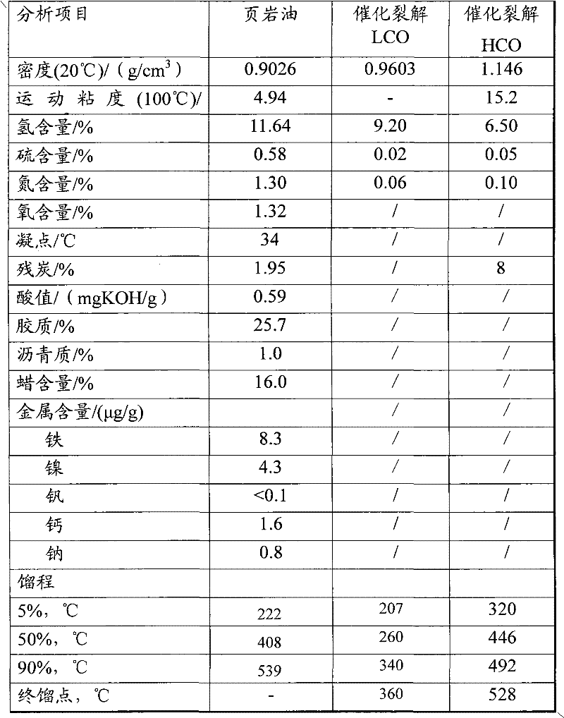
[0052] Shale oil, catalytic cracking LCO, catalytic cracking HCO (mass ratio 100:16:4) at a pressure of 15.5MPa, a reaction temperature of 380°C, in 0.625h -1 The hydrogenation reaction was carried out under the conditions of space velocity and hydrogen-to-oil ratio of 800 (v / v), and the properties of the resulting oil are shown in Table 2.

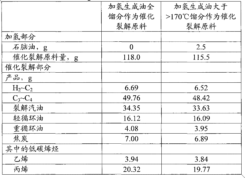
[0053] The resulting oil is distilled, and the properties of the hydrogenated tail oil after the distilled naphtha, that is, the raw material for catalytic cracking, are shown in Table 2.

[0054] Catalytic cracking of the whole distillate of the hydrogenated oil, and catalytic cracking of the hydrogenated tail oil after distilling naphtha, the reaction conditions are normal pressure, one-way, the reaction temperature is 565 ° C, the amount of atomized water is 25%, and the agent-oil ratio is 11. The material distribution of the obtained product is shown in Table 3.

[0055] Table 1 Properties of shale oil and catalytic cracking LCO and ...

Embodiment 2

[0073] Shale oil, catalytic cracking LCO, catalytic cracking HCO (mass ratio 100:5.5:1.5) at a pressure of 10.0MPa, a reaction temperature of 390°C, in 0.32h -1 The hydrogenation reaction was carried out under the conditions of space velocity and hydrogen-oil ratio of 1000 (v / v). The hydrogenated oil is distilled to distill naphtha, 170-350°C diesel oil and >350°C tail oil, the properties of which are shown in Table 6. The product distribution is shown in Table 7.

[0074] Hydrogenated tail oil was subjected to catalytic cracking, the reaction conditions were atmospheric pressure, one pass, the reaction temperature was 565°C, the amount of atomized water was 25%, and the ratio of agent to oil was 11. The material distribution of the obtained products is shown in Table 7.

Embodiment 3

[0085]Shale oil, catalytic cracking LCO, catalytic cracking HCO (mass ratio 100:11:2) at a pressure of 14.0MPa, a reaction temperature of 385°C, in 0.50h -1 The hydrogenation reaction was carried out under the conditions of space velocity and hydrogen-oil ratio of 1000 (v / v). The resulting oil is distilled to distill naphtha, low-point diesel oil and tail oil, the properties of which are shown in Table 8, and the product distribution is shown in Table 9.

[0086] Hydrogenated tail oil was subjected to catalytic cracking, the reaction conditions were normal pressure, one pass, the reaction temperature was 565°C, the amount of atomized water was 25%, and the ratio of agent to oil was 11. The material distribution of the obtained products is shown in Table 9.


PUM


Abstract

The invention relates to a deep processing method for shale oil, which comprises the following steps: placing shale oil, catalytic cracking light cycle oil and catalytic cracking heavy cycle oil into a shale oil hydrotreatment apparatus; placing the obtained hydrogenation generation oil and optional vacuum gas oil in a catalytic cracking apparatus, separating the reacted product to obtain ethane-containing dry gas, propylene and butylene-containing liquefied gas, monocyclic aromatics-rich catalytic cracking gasoline, catalytic cracking light cycle stock oil, catalytic cracking heavy cycle oil and catalytic cracking oil slurry; circulating catalytic cracking light cycle stock oil and catalytic cracking heavy cycle oil to the shale oil hydrotreatment apparatus. The deep processing method of shale oil is used for high value substances like ethane, propylene, butylene, benzene, toluene, xylene and the like, so that added value of the product can be greatly increased.

Description

technical field [0001] The invention relates to a method for combined processing of shale oil by adopting hydrotreating and catalytic cracking. Background technique [0002] With the continuous consumption of petroleum resources, oil shale has a large reserve, and the shale oil extracted from it has attracted more and more attention as an effective supplement of petroleum resources. Due to the poor quality of shale oil, it cannot be used as gasoline, diesel or chemical raw materials. Currently, it is mainly used as fuel oil with low use value. If shale oil can be further processed, the value of shale oil can be greatly increased. [0003] U.S. Patent No. 4,342,641 performs two-stage hydrogenation on the whole distillate of shale oil at a relatively low temperature of 650°F and a relatively high temperature of above 800°F. Fuel; the heavier components can be further hydrocracked to increase jet fuel production. The main defect of this patent is that there are many hydrogen...

Claims


Application Information

Patent Timeline
Patent Type & Authority Applications(China)
IPC IPC(8): C10G69/04C10G69/00
Inventor 牛传峰崔琰戴立顺高永灿杨清河聂红刘涛邵志才赵新强
Owner CHINA PETROLEUM & CHEM CORP
Why Eureka
Try Eureka