Piezoelectric vibration element, manufacturing method for piezoelectric vibration element, piezoelectric resonator, electronic device, and electronic apparatus
a manufacturing method and piezoelectric technology, applied in piezoelectric/electrostrictive/magnetostrictive devices, piezoelectric/electrostriction/magnetostriction machines, oscillators, etc., can solve problems such as deterioration of electric characteristics, frequency aging failure, and damage to cut surfaces, and achieve excellent frequency stability and satisfactory s/n ratio. , the effect of high frequency
- Summary
- Abstract
- Description
- Claims
- Application Information
AI Technical Summary
Benefits of technology
Problems solved by technology
Method used
Image
Examples
first embodiment
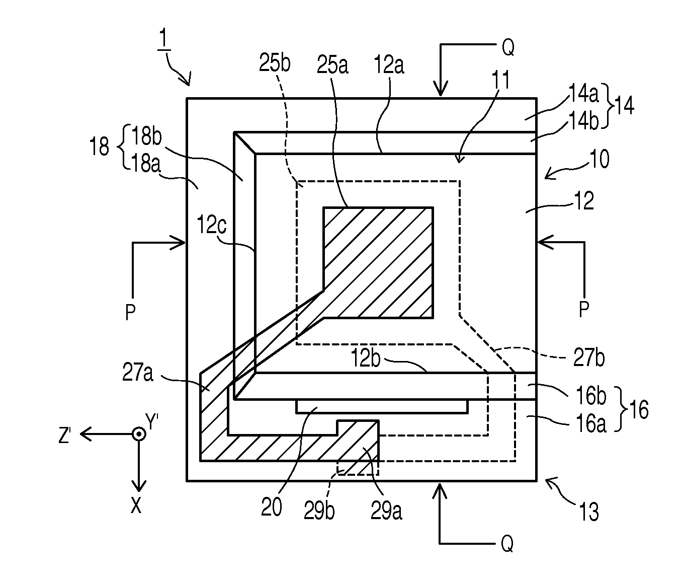
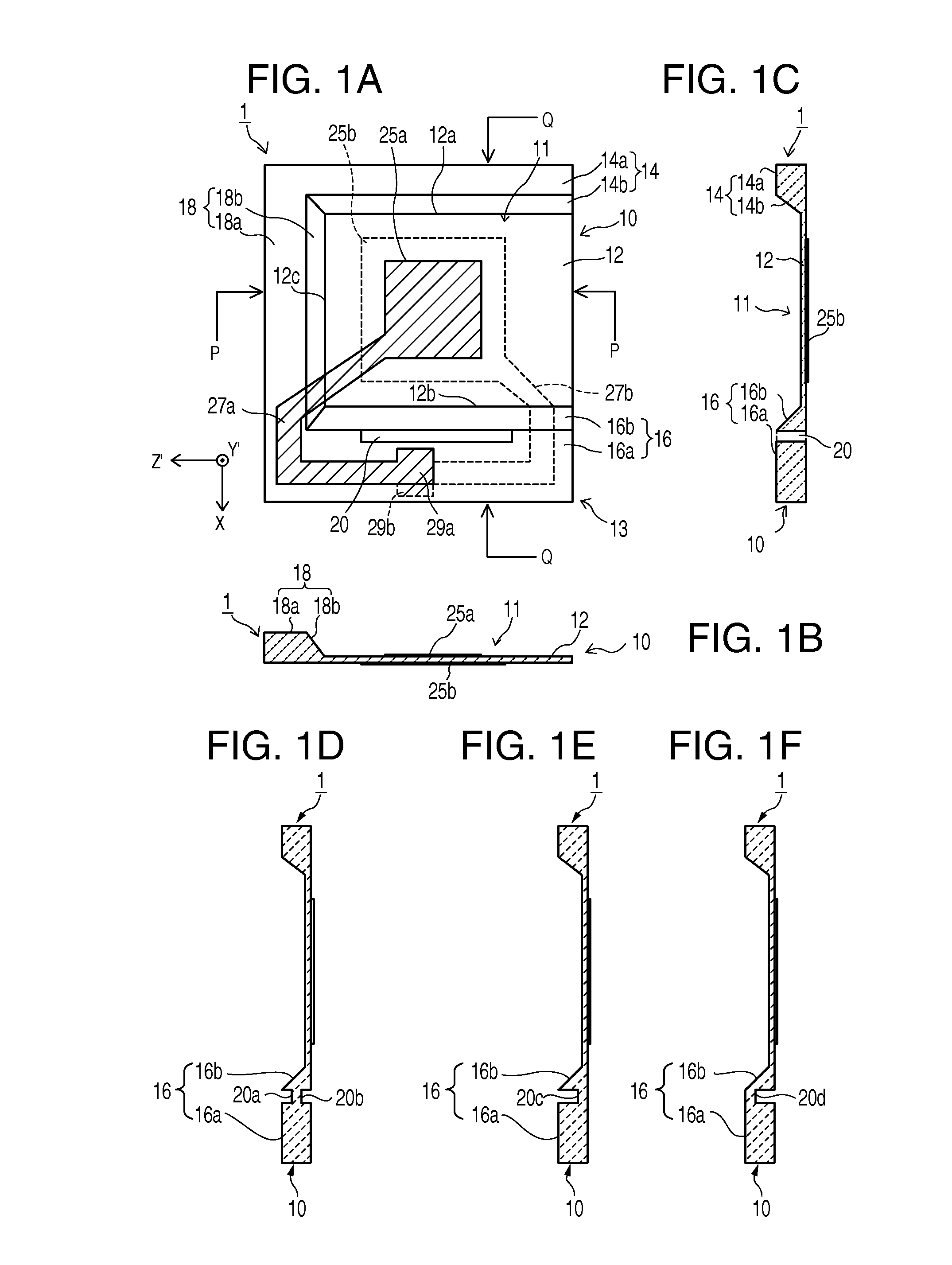
[0076]Embodiments of the invention are explained in detail below with reference to the accompanying drawings. FIGS. 1A to 1F are schematic diagrams showing the configuration of a piezoelectric vibration element according to a first embodiment of the invention. FIG. 1A is a plan view of a piezoelectric vibration element 1, FIG. 1B is a P-P sectional view of the piezoelectric vibration element 1, FIG. 1C is a Q-Q sectional view of the piezoelectric vibration element 1, and FIGS. 1D, 1E, and 1F are Q-Q sectional views showing modifications of a slit shape.
[0077]The piezoelectric vibration element 1 includes a piezoelectric substrate 10 including a thin vibration region 12 and thick sections 14, 16, and 18 connected to the vibration region 12, oscillation electrodes 25a and 25b formed to be respectively opposed to the front and the back on both principal planes of the vibration region 12, and lead electrodes 27a and 27b formed to be respectively extended from the excitation electrodes 2...
second embodiment
[0107]FIGS. 4A to 4C are schematic diagrams showing the configuration of a piezoelectric vibration element according to a second embodiment. FIG. 4A is a plan view of the piezoelectric vibration element, FIG. 4B is a P-P sectional view of the piezoelectric vibration element, and FIG. 4C is a Q-Q sectional view of the piezoelectric vibration element.
[0108]A piezoelectric vibration element 2 is different from the piezoelectric vibration element 1 in a position where the slit 20 for stress relaxation is provided. In this example, the slit 20 is formed in the inclined section 16b separating from the end edge of the one side 12b of the thin vibration region 12. The slit 20 is provided separating from both the end edges of the inclined section 16b rather than being formed in the inclined section 16b along the one side 12b of the vibration region 12 such that one end edge of the slit 20 is in contact with the one side 12b. An extremely thin inclined section 16bb connected to the end edge o...
third embodiment
[0110]FIGS. 5A to 5E are schematic diagrams showing the configuration of a piezoelectric vibration element according to a third embodiment. FIG. 5A is a plan view of the piezoelectric vibration element, FIG. 5B is a P-P sectional view of the piezoelectric vibration element, FIG. 5C is a Q-Q sectional view of the piezoelectric vibration element, and FIG. 5D is a plan view of the piezoelectric vibration element.
[0111]A piezoelectric vibration element 3 is different from the piezoelectric vibration element 1 shown in FIGS. 1A to 1F in that the first slit 20a is provided in the plane of the second thick section main body 16a and the second slit 20b is formed in the plane of the inclined section 16b to provide the two slits for stress relaxation. The purpose of forming the separate slits (the first slit 20a and the second slit 20b) in the plane of the second thick section main body 16a and in the plane of the inclined section 16b is already explained above. Therefore, the explanation is ...
PUM
| Property | Measurement | Unit |
|---|---|---|
| frequency | aaaaa | aaaaa |
| frequency | aaaaa | aaaaa |
| angle | aaaaa | aaaaa |
Abstract
Description
Claims
Application Information
 - R&D
- Intellectual Property
- Life Sciences
- Materials
- Tech Scout
- Unparalleled Data Quality
- Higher Quality Content
- 60% Fewer Hallucinations
Browse by: Latest US Patents, China's latest patents, Technical Efficacy Thesaurus, Application Domain, Technology Topic, Popular Technical Reports.
© 2025 PatSnap. All rights reserved.Legal|Privacy policy|Modern Slavery Act Transparency Statement|Sitemap|About US| Contact US: help@patsnap.com


