
Arrangement of an antenna on a container

an antenna carrier and container technology, applied in the direction of antennas, containers, large containers, etc., can solve the problems of unfavorable control of temperature-related pressure of the container volume, inability to reliably prevent an unauthorized intervention for manipulation of the system, and damage to the system attached to the exterior walls of the containers, etc., to achieve the effect of facilitating a temperature-related pressure equalization of the container volum

Inactive Publication Date: 2011-06-07
REEL REINHEIMER ELEKTRONIK
View PDF10 Cites 3 Cited by
  • Summary
  • Abstract
  • Description
  • Claims
  • Application Information

AI Technical Summary

Benefits of technology

[0012]It is therefore an object of the invention to provide an antenna arrangement for a steel container which is protected against damage and unauthorized outside manipulation.
[0013]Another object of the invention is to provide an antenna arrangement for a steel container which assures reliable communication between the exterior world and electronic systems arranged in the interior of the container for determining the container location and monitoring the container content.
[0014]A further object of the invention is to provide an antenna arrangement for a steel container which may be retrofitted and / or exchanged in a simple manner.
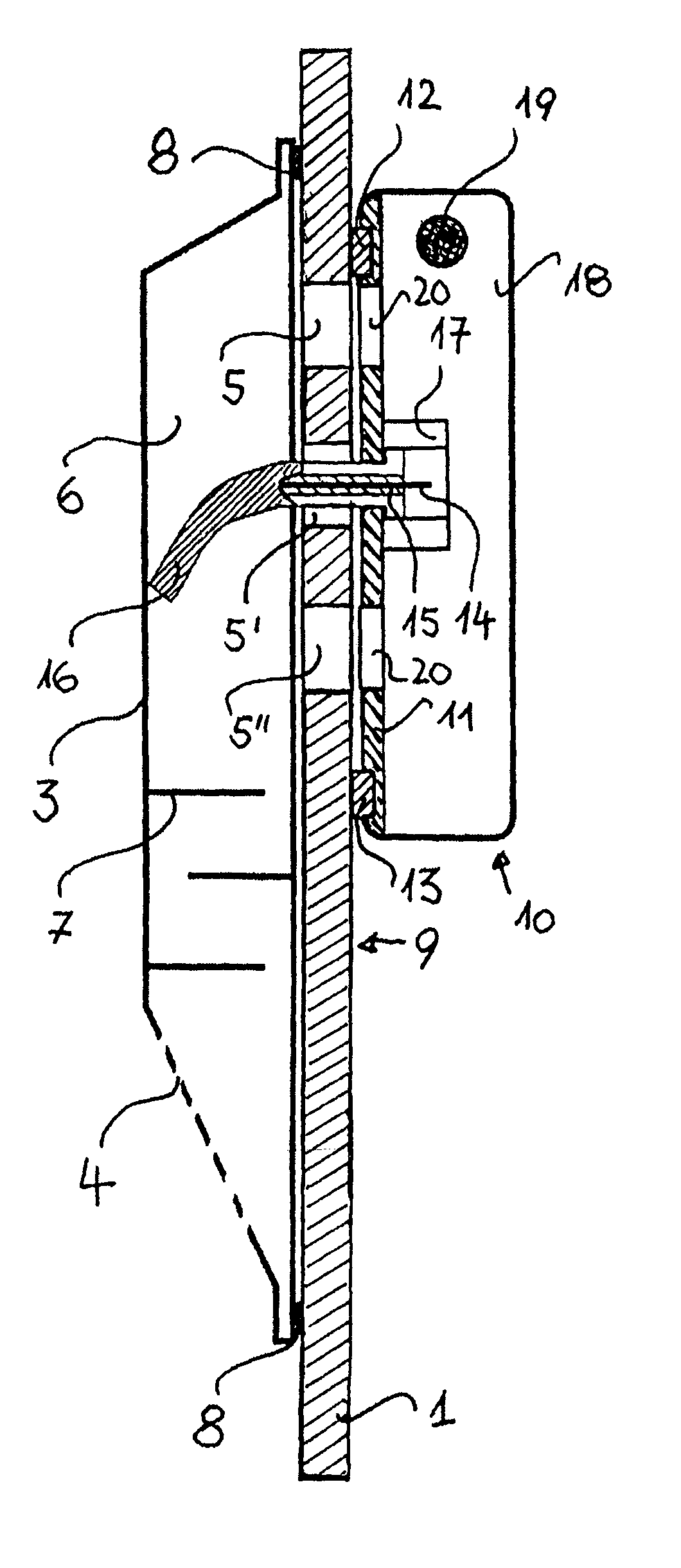
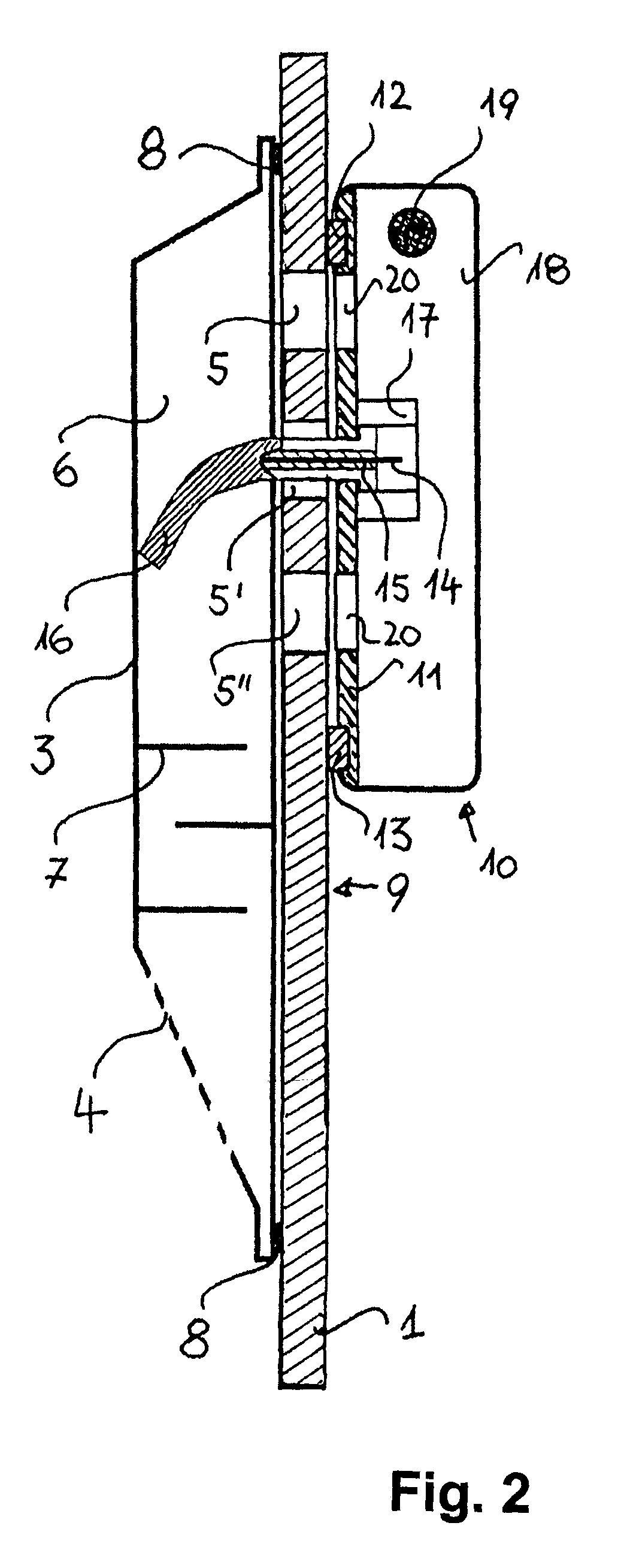
[0016]The invention makes use of the fact that standardized containers are each provided on at least one side wall with ventilation openings, which facilitate a temperature-related pressure equalization of the container volume with the exterior environment. The ventilation openings typically comprise a pattern of holes having a diameter of approximately 8 mm. A nonremovable cover which protects against water spray is placed externally over this pattern. The cover forms a closed cavity in front of the hole pattern, which is protected on the bottom against penetration of water spray by webs arranged offset in height and location relative to one another. The cover is provided with slots for the air entry underneath. The cover is inserted into an inwardly pointing profiled segment of the container wall, so that it is protected against impacts during loading. The cavity in front of the ventilation openings has a height of approximately 2.5 cm.
[0017]Surprisingly, it has been found that the existing cavity in front of the ventilation openings is sufficient, with appropriate construction and arrangement of the antenna carrier and the antenna shape, to be able to send or receive a transmission between the interior of the container and the outside. It is only necessary to ensure that the cover is comprised of plastic. The closing of individual ventilation openings by the antenna arrangement does not affect the necessary pressure equalization.

Problems solved by technology

In addition, expensive container contents must possibly be monitored against theft or manipulation of the products.
Systems attached to the exterior walls of the containers may be damaged during loading and stacking of the containers.
In addition, the outside location may not reliably prevent an unauthorized intervention for manipulation of the system.
The antennas extending between sealing lips of the door panels may be damaged on their external ends when the doors are closed, and are subject to additional strains when the door panels are moved.

Method used


Image

  • Arrangement of an antenna on a container
  • Arrangement of an antenna on a container
  • Arrangement of an antenna on a container

Examples


Embodiment Construction

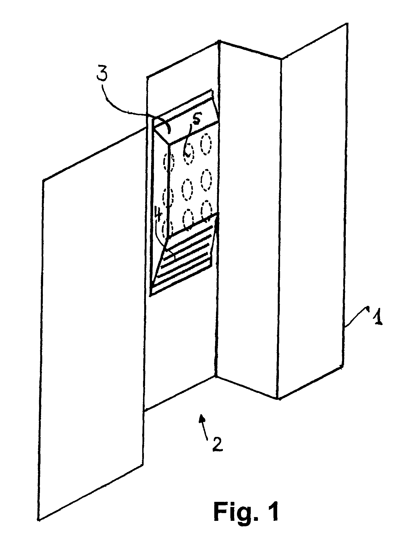
[0021]FIG. 1 shows a detail of a trapezoidally profiled container wall 1 viewed from the outside. A cover 3 is inserted in an inwardly facing profile segment 2 of the container wall 1. The cover 3 is connected permanently to the container wall 1 by fasteners (not shown in greater detail). Slots 4 are arranged in the lower area of the cover 3 as air passages. A pattern of ventilation openings 5, which are protected by the cover 3, is depicted in the upper area.

[0022]FIG. 2 shows a cross-section through the container wall 1 in the area of the cover 3. Three ventilation openings 5, 5′, 5″ from the pattern depicted in FIG. 1, which lie one underneath another, are shown in the container wall 1. The cover 3 forms a cavity 6 in front of the ventilation openings 5, 5′, 5″. Three webs 7, which are arranged offset in height and laterally relative to one another, are provided below the cavity 6. These staggered webs 7 serve to prevent sprayed water from entering the cavity 6 through the slots ...


PUM


Abstract

An antenna carrier (10) with an antenna (14) for electromagnetic radiation to be fastened to a wall (1) of a container composed of steel plate and having ventilation openings (5) which are covered on the exterior side of the container wall (1) by a cover (3) which protects against sprayed water, and which forms a cavity (6) in front of the ventilation openings (5), in which the cover (3) is composed of plastic, the antenna (14) projects through a ventilation opening (5) into the cavity (6) formed by the cover, the antenna carrier (10) is fastened on the interior side (9) of the container wall (1), and the antenna carrier (10) is the ground reference surface of the antenna (14) and is constructed as a magnetizable metal plate (11).

Description

CROSS REFERENCE TO RELATED APPLICATIONS[0001]This application is a continuation of international patent application no. PCT / DE2007 / 000846, filed May 10, 2007 designating the United States of America and published in German on Dec. 6, 2007 as WO 2007 / 137551, the entire disclosure of which is incorporated herein by reference. Priority is claimed based on Federal Republic of Germany patent application no. DE 10 2006 025 214.4, filed May 29, 2006.BACKGROUND OF THE INVENTION[0002]The present invention relates to an antenna carrier with an antenna for electromagnetic radiation to be fastened on a wall of a container made of steel plate and having ventilation openings which are covered on the exterior side of the container wall by a cover which protects against sprayed water, with the cover forming a cavity in front of the ventilation openings.[0003]Containers comprised of steel plate are typical for the worldwide transport of semifinished and finished products. The containers have closabl...

Claims


Application Information

Patent Timeline
Patent Type & Authority Patents(United States)
IPC IPC(8): H01Q1/32H01Q1/42H01Q5/10
CPCB65D88/741B65D90/00B65D2203/10
Inventor REINHEIMER, HANS-JOERGBUCHWEITZ, KNUTHEIERLI, JAKOB
Owner REEL REINHEIMER ELEKTRONIK
Learn More