Measurement apparatus, exposure apparatus, and device manufacturing method

a technology of measurement apparatus and exposure apparatus, which is applied in the direction of photomechanical treatment, instruments, printing, etc., can solve the problems of polarization state, non-negligeable influence of vibration, and various problems of conventional schemes described abov

Inactive Publication Date: 2011-06-07
CANON KK
View PDF11 Cites 9 Cited by
  • Summary
  • Abstract
  • Description
  • Claims
  • Application Information

AI Technical Summary

Benefits of technology

[0018]It is an object of the present invention to provide a measurement apparatus which measures the optical characteristics of an optical system employed in, for example, an exposure apparatus quickly and accurately.
[0020]The present invention can provide a measurement apparatus which measures the optical characteristics of an optical system employed in, for example, an exposure apparatus quickly and accurately.

Problems solved by technology

Even when an illumination system controls the exposure light to a desired polarization state, however, distortion of a lens caused by holding the lens or the heat in the lens, use of a birefringent material such as fluorite, reflection of a mirror, and the like may change the polarization state within the projection optical system.
The conventional schemes described above, however, have various problems.
The interferometer for measurements disclosed in Japanese Patent Laid-Open Nos. 2-116732, 2002-71515, and 2004-257854 is not appropriate for measurement in the exposure apparatus because its exposure light source has a very short coherent length, in addition to its long, complicated optical path as a non-common path, so that the influence by vibration is non-negligible.
With only two orthogonal linearly polarized beams, the retardation and azimuth of birefringence as the polarization aberration of the projection optical system cannot be calculated accurately.
In other words, this method requires two CCDs, which is costly.
This may hinder accurate measurement.
Depending on the alignment accuracy, the correspondence between unpolarization aberration and polarization aberration can change, disabling accurate phase measurement.
In addition, this alignment error can leads to deterioration in accuracy, and become a big error-coming factor when highly accurate measurements are asked for.
However, the scheme disclosed in Japanese Patent Laid-Open Nos. 2004-61515 and 2006-237617 does not provide a system that can measure reference polarization aberration in the apparatus.
Hence, the system cannot cope with a real-time change of information on the reference polarization aberration, and thus cannot detect polarization aberration information quickly and accurately.
Therefore, polarization aberration cannot be calculated accurately.
In recent years, aberration (exposure aberration), or unpolarization aberration and polarization aberration that change (change over time) in a real time as the optical system generates heat upon exposure, has become a major issue.

Method used


Image

  • Measurement apparatus, exposure apparatus, and device manufacturing method
  • Measurement apparatus, exposure apparatus, and device manufacturing method
  • Measurement apparatus, exposure apparatus, and device manufacturing method

Examples


first embodiment

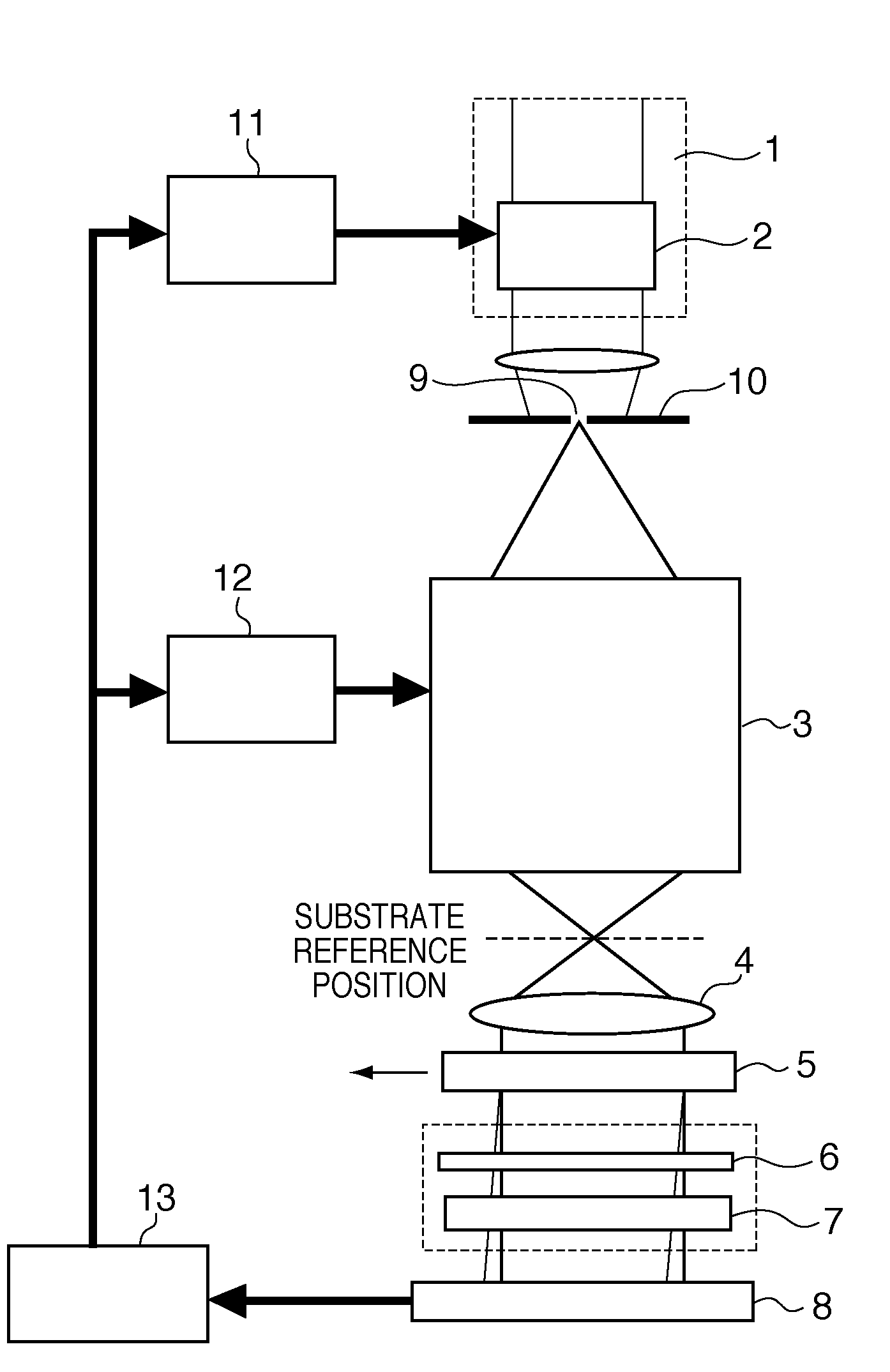
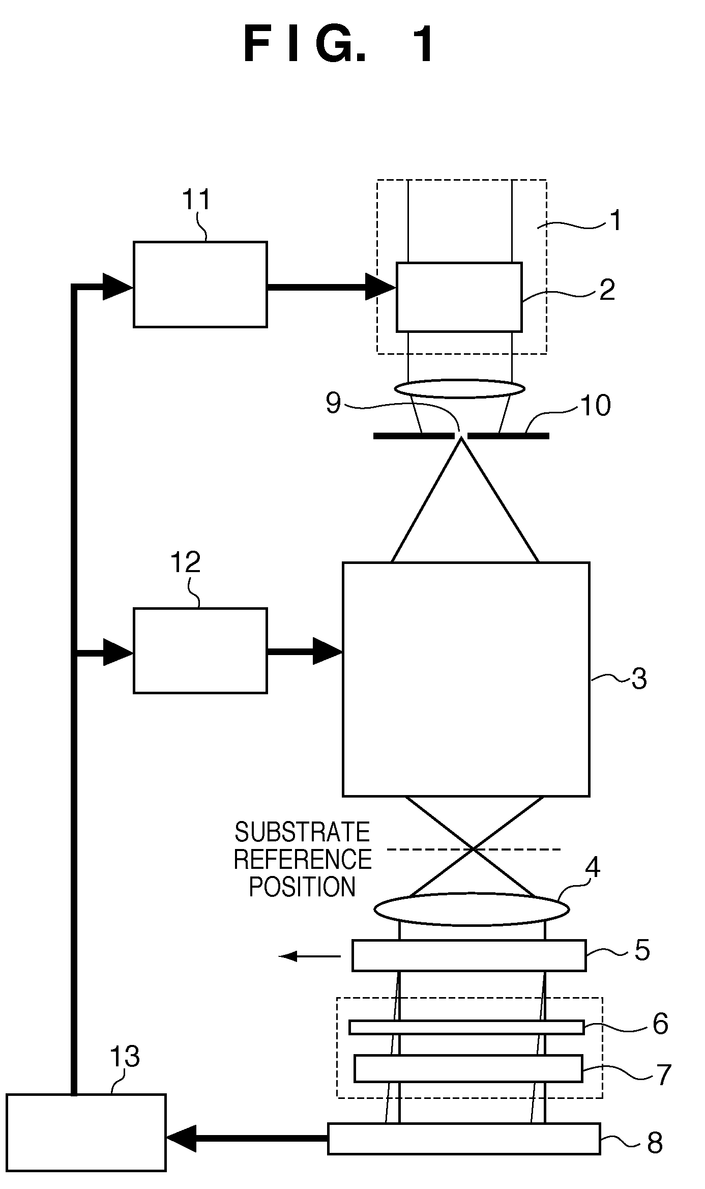
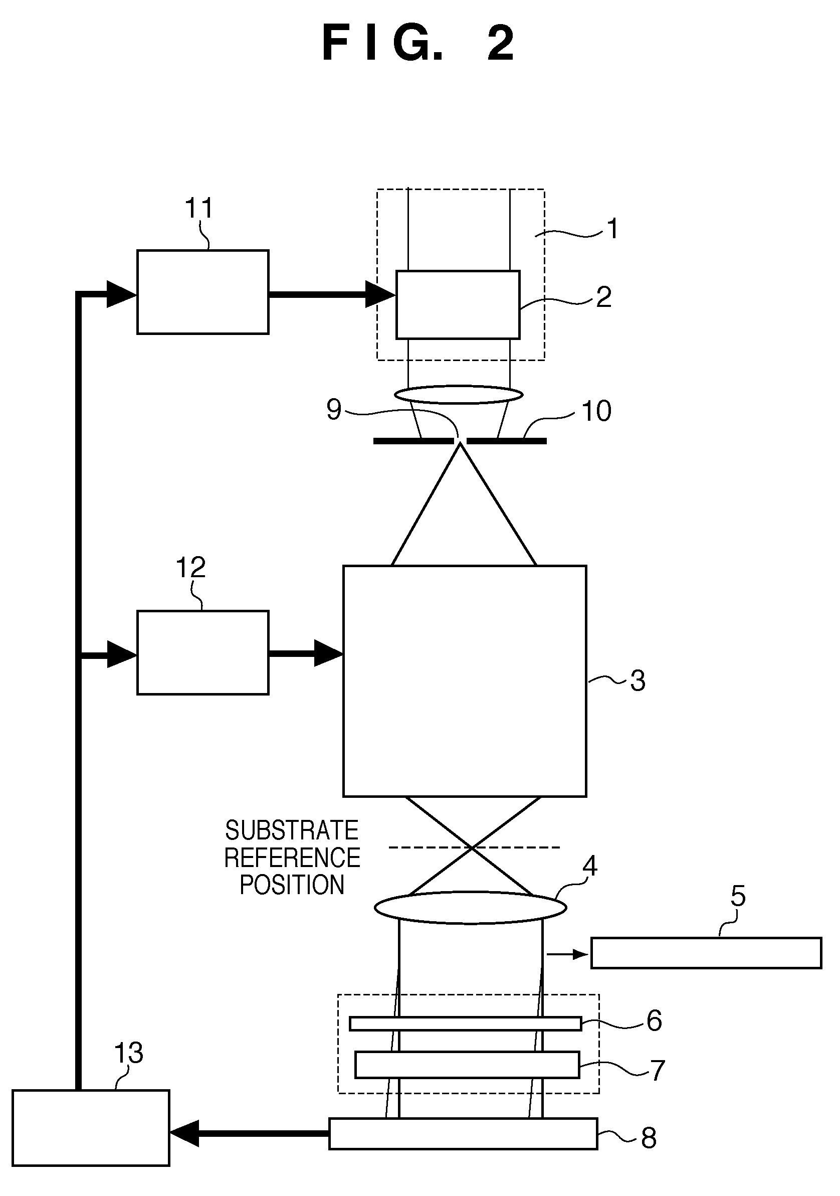
[0042]An exposure apparatus incorporating a measurement apparatus of the first embodiment of the present invention will be described with reference to FIGS. 1 and 2. In the first embodiment, the detection target, the optical characteristics of which are to be measured, is the projection optical system of an exposure apparatus, in which only the wavefront dividing unit is detachable. The measurement apparatus measures “unpolarization aberration” which does not depend on the polarization of illumination light and is the same as conventional wavefront aberration, and retardation and azimuth of birefringence as “polarization aberration” which changes depending on the polarization of the illumination light.

[0043]In normal exposure, light provided by an illumination system 1 illuminates an original (exposure reticle) to project the pattern of the original onto a substrate, placed at the substrate reference position, through a projection optical system 3. The substrate reference position i...

second embodiment

[0094]An exposure apparatus incorporating a measurement apparatus of the second embodiment of the present invention will be described. The measurement apparatus of the second embodiment serves to measure the optical characteristics of a projection optical system 3 and comprises a diffraction grating 55 serving as a detachable wavefront dividing unit. The diffraction grating 55 can be inserted in and removed from the optical path. The most characteristic feature of this embodiment resides in the following respect. More specifically, when the diffraction grating 55 is in the optical path, the apparatus can perform measurement using interference. When the diffraction grating is not in the optical path, the apparatus can perform polarization measurement using intensity change.

[0095]First, the diffraction grating 55 is inserted in the optical path, and interference measurement is performed. Incident polarized light formed by a polarization controller 2 arranged in an illumination system ...

third embodiment

[0107]An exposure apparatus incorporating a measurement apparatus of the third embodiment of the present invention will be described with reference to FIG. 9. The measurement apparatus of the third embodiment comprises a detachable diffraction grating 95, waveplate 6, polarizer 7, and detector 8 on the original (reticle) side.

[0108]In the third embodiment, a reflecting mirror 914 reflects light transmitted through a projection optical system 3, and the detector 8 arranged on the original (reticle) side detects a wavefront transmitted through the projection optical system 3 again. When compared to measurement on the substrate side of the first and second embodiments, measurement of the third embodiment is advantageous in that, for example, since the light is transmitted through the projection optical system twice, the aberration amount is doubled, since the numerical aperture is small, the light can be collimated easily, the arranged has a degree of freedom. The third embodiment serv...


PUM


Abstract

A measurement apparatus includes a polarization controller which controls polarization of light, a wavefront dividing unit which divides a wavefront of the light, a polarizing unit which polarizes the light, a detector which detects the light, a first driving unit which moves the wavefront dividing unit with respect to the detector, a second driving unit which moves the polarizing unit with respect to the detector, and a processor which calculates the optical characteristics of the detection target using a detection results obtained when the wavefront dividing unit is positioned in the optical path and a detection result obtained when the wavefront dividing unit is positioned outside the optical path.

Description

BACKGROUND OF THE INVENTION[0001]1. Field of the Invention[0002]The present invention relates to a measurement apparatus, exposure apparatus, and device manufacturing method.[0003]2. Description of the Related Art[0004]In the lithography process to manufacture a device such as a semiconductor device, an exposure apparatus is used to transfer the pattern on a reticle (original) onto a wafer (substrate) coated with a resist. Along with the trend toward integrated circuits with a higher density and higher degree of integration, the exposure apparatus must have higher resolution, and accordingly the wavelength of the exposure light is becoming shorter. More specifically, as the light source of the exposure apparatus, use of a KrF excimer laser (wavelength: 248 nm) and an ArF excimer laser (wavelength: 193 nm) has become popular to replace a mercury lamp.[0005]An increase in numerical aperture (NA) of the projection optical system of the exposure apparatus can also increase the resolutio...

Claims


Application Information

Patent Timeline
Patent Type & Authority Patents(United States)
IPC IPC(8): G03B27/72G03B27/54
CPCG03F7/706G03F7/70566
Inventor OHSAKI, YUMIKO
Owner CANON KK
Why Eureka
Try Eureka