
Thread removal device

a thread removal and thread technology, applied in the field of thread removal, can solve the problems of inconvenient and time-consuming use of two separate tools at the same time, and achieve the effect of reducing the challenges of seam ripping

Active Publication Date: 2011-06-14
HEFFNER LORRI L
View PDF4 Cites 11 Cited by
  • Summary
  • Abstract
  • Description
  • Claims
  • Application Information

AI Technical Summary

Benefits of technology

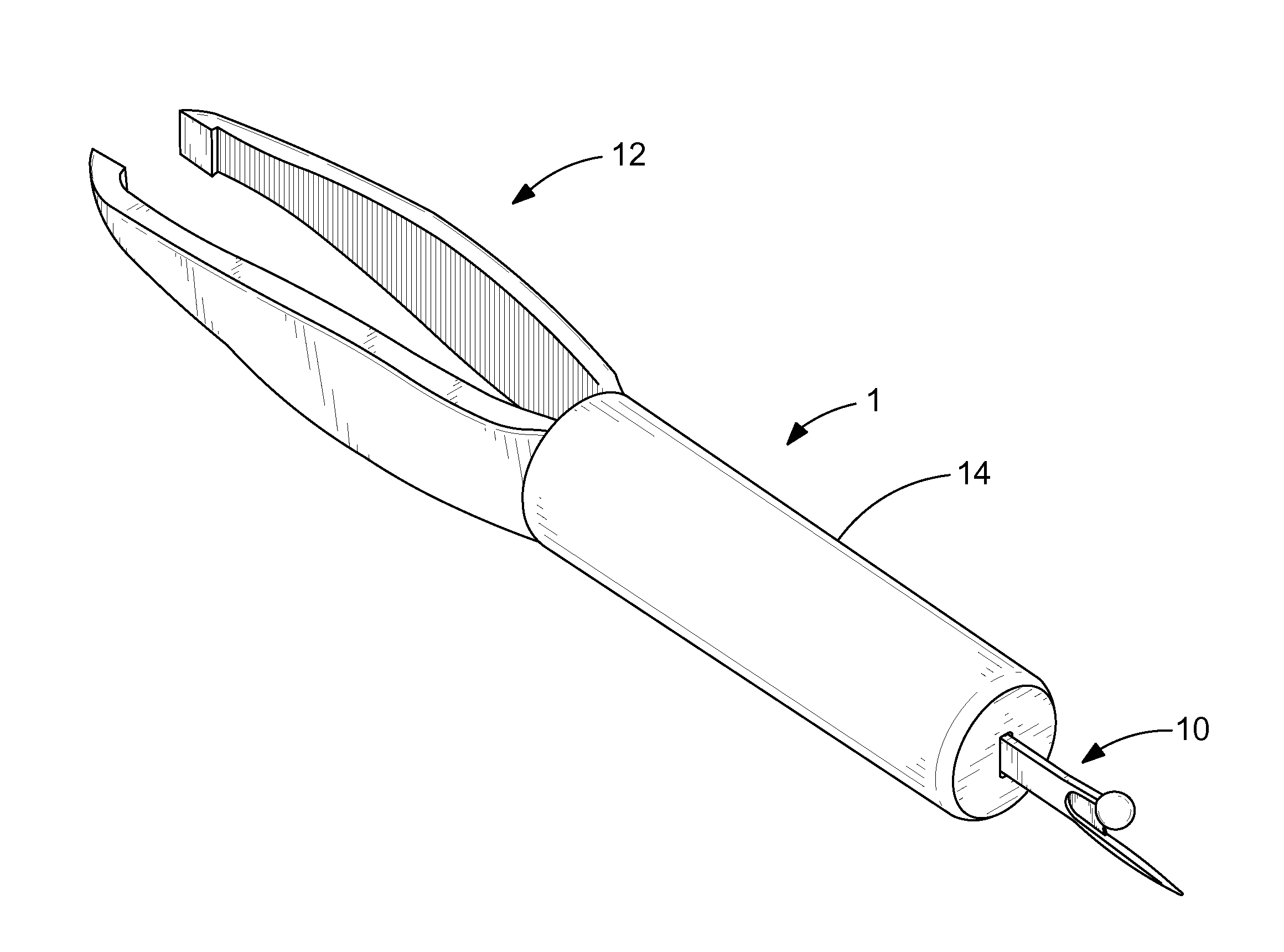
[0007]The present invention provides a thread removal device, which reduces the challenges associated with seam ripping. The thread removal device preferably includes a thread cutter, a grasping implement and a finger base. The thread cutter preferably includes a blade projection, a safety projection and a cutter base. The blade projection and the safety projection extend from one end of the cutter base to form a substantial Y-shape. A web surface of the blade projection is sharpened for cutting threads.
[0008]An end of the blade projection preferably comes to a point for insertion under a thread. The safety projection protects a user from cutting themselves or the sewn article they are working on. It is preferable to terminate an end of the safety projection with a safety cap. A cover cap may be used to protect an end of the thread cutter.
[0012]Finally, it is another object of the present invention to provide a thread removal device, which has the unexpected result of not requiring a sewer to remove their eye focus from sewing work, while cutting threads and removing the thread remnants.

Problems solved by technology

It is inconvenient and time consuming to use two separate tools consecutively.

Method used


Image

  • Thread removal device
  • Thread removal device
  • Thread removal device

Examples


Embodiment Construction

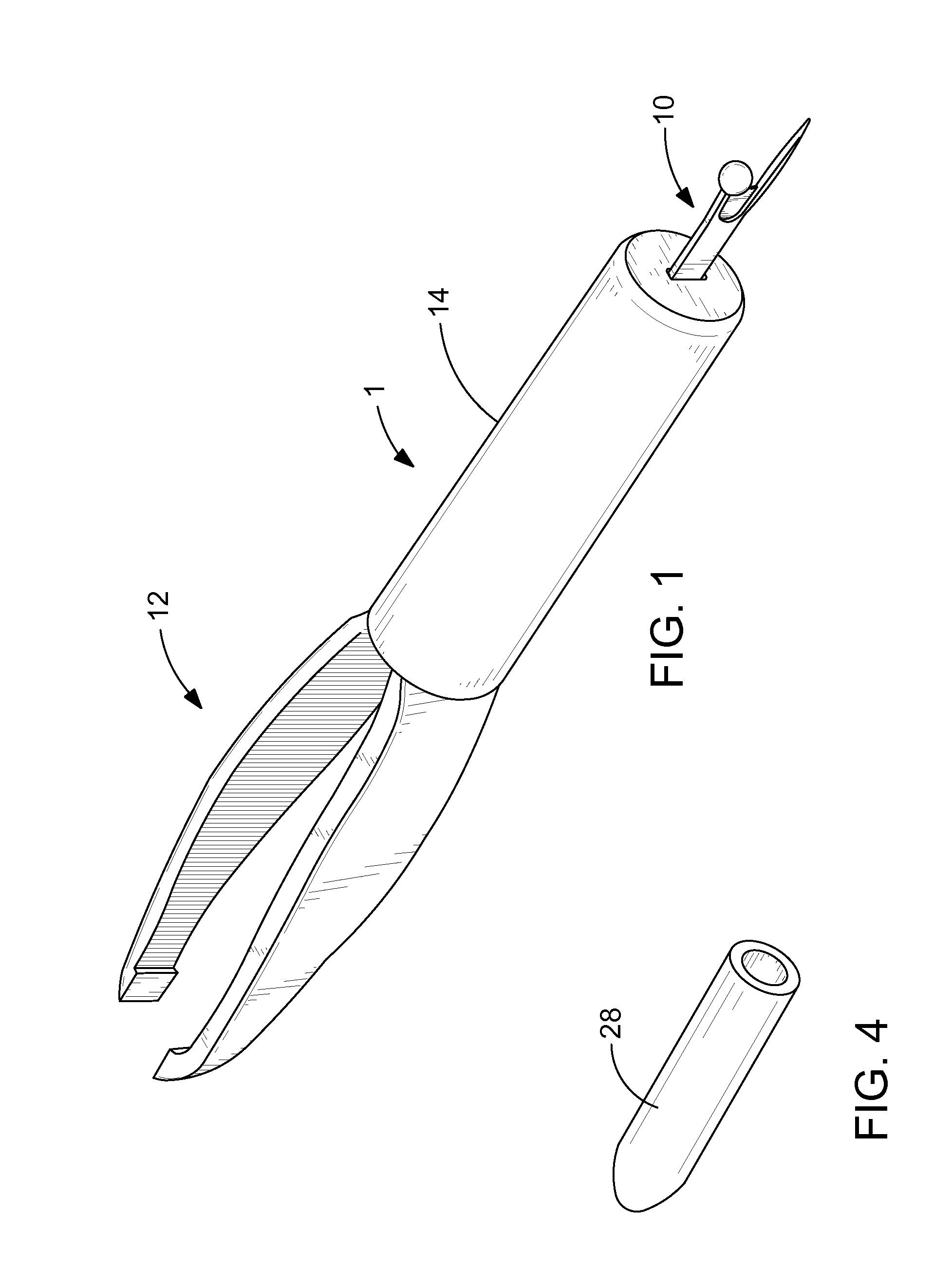
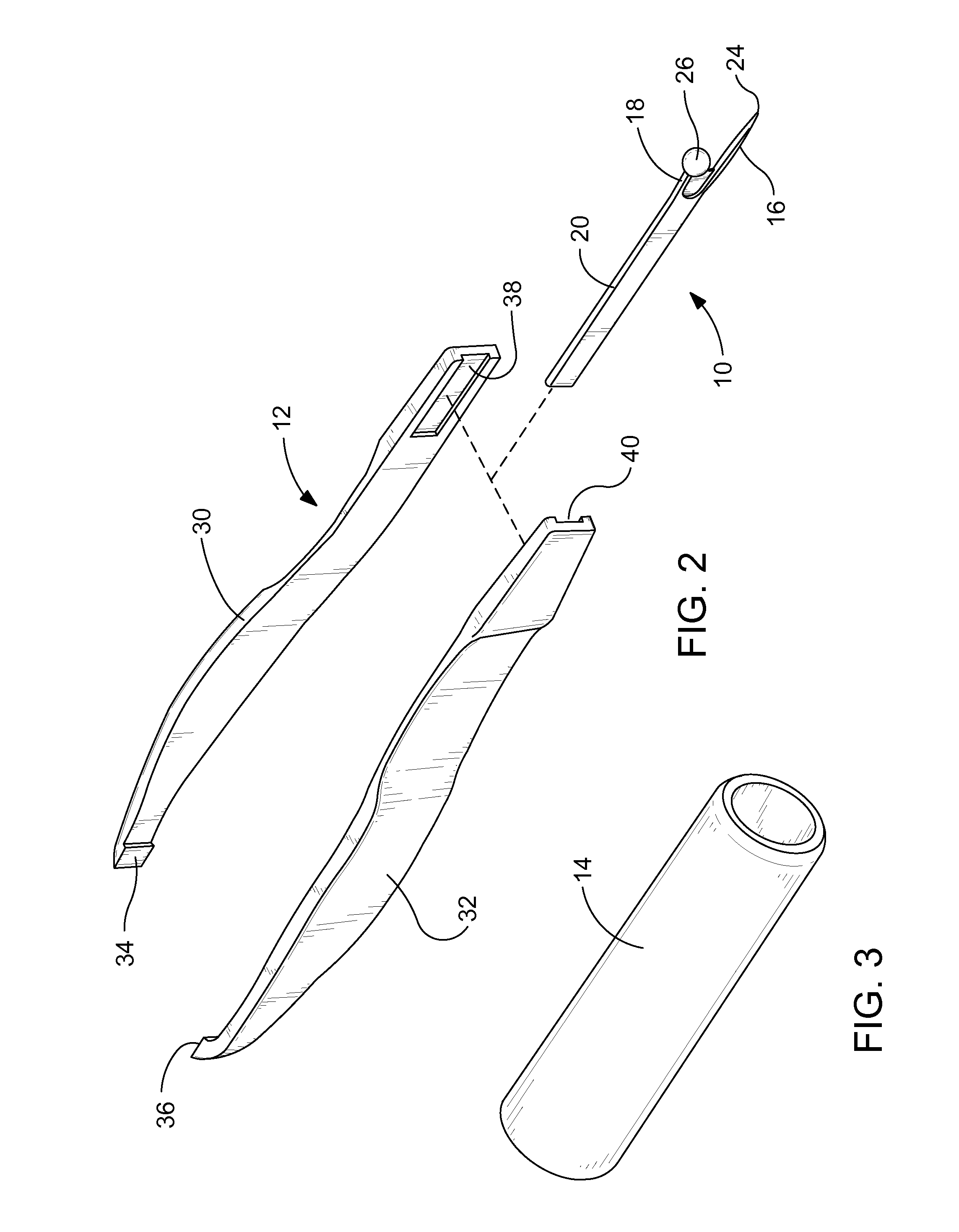
[0020]With reference now to the drawings, and particularly to FIG. 1, there is shown a perspective view of a thread removal device 1. With reference to FIGS. 2-6, the thread removal device 1 preferably includes a thread cutter 10, a grasping implement 12 and a finger base 14. The thread cutter 10 preferably includes a blade projection 16, a safety projection 18 and a cutter base 20. The blade projection 16 and the safety projection 18 extend from one end of the cutter base 20 to form a substantial Y-shape.

[0021]A web area 22 between the blade projection 16 and the safety projection 18 is sharpened for cutting threads. However, substantially all of the inside surface 23 of the blade projection may also be sharpened. An end of the blade projection 16 preferably comes to a point 24 for insertion under a thread. The safety projection 18 protects a user from cutting themselves or a sewn article they are working on. It is preferable to terminate an end of the safety projection 18 with a s...


PUM


Abstract

A thread removal device preferably includes a thread cutter, a grasping implement and a finger base. The thread cutter preferably includes a blade projection and a safety projection extending from a cutter base. A cover cap may be placed over the thread cutter. The grasping implement includes a first grasping leg and a second grasping leg. A first contact pad is formed on one end of first grasping leg and a second contact pad is formed on one end of the second grasping leg. The first and second contact pads are biased away from each other. The other ends of the first and second grasping legs receive cutter base. The first grasping leg, the second grasping leg and the thread cutter may be attached to each other with any suitable assembly method. The finger base may be retained over grasping implement and the thread cutter.

Description

CROSS-REFERENCES TO RELATED APPLICATIONS[0001]This is a nonprovisional application taking priority from provisional application No. 61 / 107,094, filed on Oct. 21, 2008.BACKGROUND OF THE INVENTION[0002]1. Field of the Invention[0003]The present invention relates generally to removing threads from a sewn article and more specifically to a thread removal device, which reduces the challenges associated with seam ripping.[0004]2. Discussion of the Prior Art[0005]A sewer, who wishes to remove unwanted threads from a sewn seam needs a sharp instrument to cut through the threads to remove them from the sewn article. The sewer removing the thread will oftentimes use a universal seam ripper. A universal seam ripper has the nuisance value of not offering a thread removal feature. The universal seam ripper cuts the thread and leaves thread remnants, yet, the thread remnants still need to be removed. Many times sewers will attempt to use their fingers to grasp these threads and pull them out. The...

Claims


Application Information

Patent Timeline
IPC IPC(8): B26B27/00B25F1/00
CPCB25F1/00D05B89/00B26B27/00
Inventor HEFFNER, LORRI L.
Owner HEFFNER LORRI L
Learn More