Double ended peg

a double-ended, peg technology, applied in the direction of washing apparatus, garments, applications, etc., to achieve the effect of high mechanical strength and rigidity, good dimensional stability, and sufficient biasing for

Inactive Publication Date: 2011-06-14
RANKIN IAN +3
View PDF15 Cites 3 Cited by
  • Summary
  • Abstract
  • Description
  • Claims
  • Application Information

AI Technical Summary

Benefits of technology

[0025]Preferably, the outer surface of each member is concave. Advantageously, the concave shape of the outer surface increases the inner angle of each handle, the inner angle being the angle between the inner surfaces of each member forming the handle, the increase in inner angle enabling the fastener to be opened to accommodate larger items than a fastener with a smaller inner angle.

Problems solved by technology

Depending on the user, this may require the use of two hands which can be troublesome, especially when the other hand is otherwise occupied holding what is to be fastened.

Method used


Image

  • Double ended peg
  • Double ended peg
  • Double ended peg

Examples


first embodiment

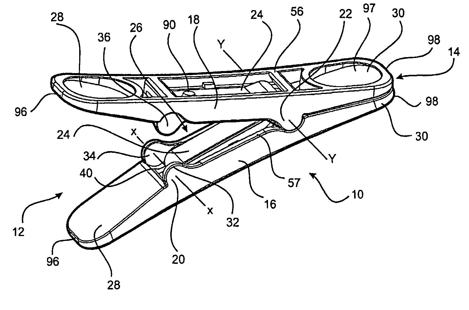
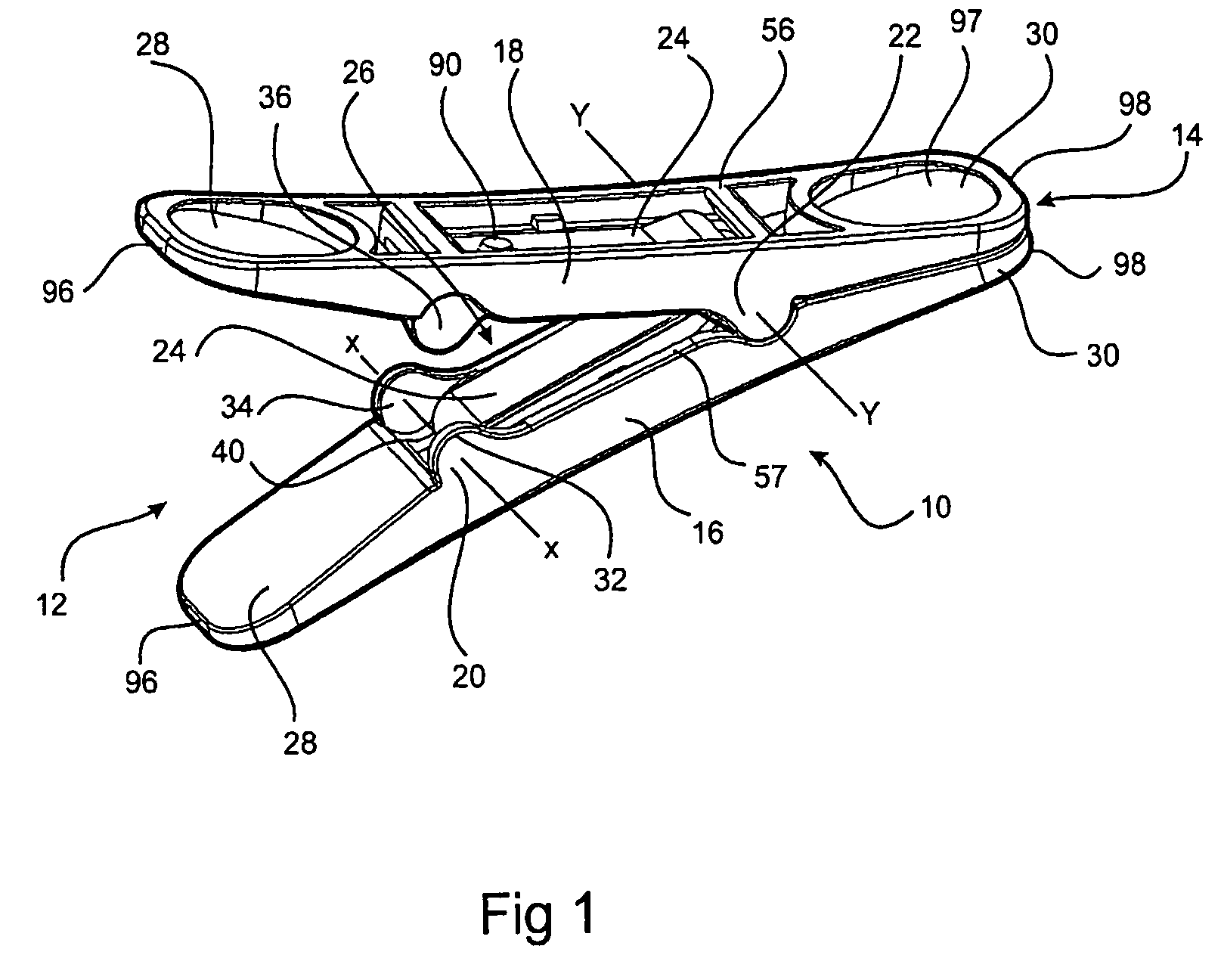
[0046]In FIGS. 1 to 7 there is shown a fastener 10 in accordance with the present invention, the fastener 10 comprising a first end 12 and a second end 14. The fastener 10 includes a first member 16 and a second member 18, a first fulcrum 20 and a second fulcrum 22 and a biasing means 24. Jaws 26 are provided between the first fulcrum 20 and the second fulcrum 22. A first handle 28 is provided at the first end 12 and a second handle 30 is provided at the second end 14. As best seen in FIG. 2, first member 16 and second member 18 are identical in shape.

[0047]The first fulcrum 20 includes three arcuate discs 32, 34, 36 arranged longitudinally and substantially normally to the first member 16 and the second member 18. Alternate discs are provided on the first member 16 and second member 18 with discs 32 and 36 being provided on the first member 16 and disc 34 being provided on the second member 18. Each disc 32, 34, 36 engages a respective complementary recess 38, 40, 42 in the opposin...

second embodiment

[0063]In FIGS. 8 to 16 there is shown a fastener 110 in accordance with the present invention. The fastener 110 comprises a first end 112 and a second end 114. The fastener 110 includes a first member 116 and a second member 118, a first fulcrum 120 and a second fulcrum 122 and a biasing means 124. Jaws 126 are provided between the first fulcrum 120 and the second fulcrum 122. A first handle 128 is provided at the first end 112 and a second handle 130 is provided at the second end 114. As best seen in FIG. 11, first member 16 and second member 18 are identical in shape.

[0064]The first fulcrum 120 includes four arcuate discs 132, 134, 136, 138 arranged longitudinally and substantially normally to the first member 116 and the second member 118. Each disc 132, 134, 136, 138 engages a respective complementary recess 140, 142, 144, 146 in the opposing member such that the first member 116 and the second member 118 may pivot thereabout on a pivot axis X-X through the centre of curvature o...


PUM


Abstract

In accordance with the present invention, there is provided a fastener with a first end and a second end, the fastener including a first member, a second member and biasing means, at least a first portion of the basing means being substantially parallel to at least a portion of the first member and at least a second portion of the basing means being substantially parallel to the at least a portion of the second member, the first and second members relatively pivotable at a first fulcrum intermediate the first and second ends and at a second fulcrum intermediate the first and second ends wherein the first fulcrum and the second fulcrum are spaced apart relative to each other, jaws located between the first fulcrum and the second fulcrum, a first handle at the first end of the fastener and a second handle at the second end of the fastener wherein squeezing of the first handle pivots the first and second members about the first fulcrum to open the jaws against closing bias provided by the biasing means and squeezing of the second handle pivots the first and second members about the second fulcrum to open the jaws against closing bias provided by the biasing means.

Description

FIELD OF THE INVENTION[0001]The present invention relates to a fastener of a type suitable for use as a peg in fastening clothes or the like to a line.BACKGROUND ART[0002]Fasteners such as those suitable for use as pegs in fastening clothes or the like to a line are known to include two elongate members and a spring mechanism with a fastening portion or jaws at one end of the peg and an operating portion or handle at the other end of the peg. Such fasteners are often stored in a bucket or box or similar container and when required, a user will pull one out of the container to use in the known manner. It is often the case that the peg is pulled out ‘upside-down’ with the user holding the end with the jaws rather than the end with the handle, thereby requiring the fastener to be turned around. Depending on the user, this may require the use of two hands which can be troublesome, especially when the other hand is otherwise occupied holding what is to be fastened.[0003]It would be an ad...

Claims


Application Information

Patent Timeline
Patent Type & Authority Patents(United States)
IPC IPC(8): D06F55/02A44B99/00
CPCD06F55/02F16B2/10F16B2/20Y10T24/44385Y10T24/3439Y10T24/344Y10T24/3443Y10T24/44393
Inventor RANKIN, IANRANKIN, ROCHELLESTRICKLAND, MARKSTRICKLAND, MIRANDA
Owner RANKIN IAN
Why Eureka
Try Eureka