Flat air filter element and air filter

a technology of air filter and air filter element, which is applied in the direction of machine/engine, combustion-air/fuel-air treatment, separation process, etc., can solve the problems of insufficient expansion of air filter space, reduce the power of internal combustion engine, etc., to achieve low cost, low pressure loss, and good sealing seat

Active Publication Date: 2020-05-26
MANN HUMMEL GMBH
View PDF41 Cites 4 Cited by
  • Summary
  • Abstract
  • Description
  • Claims
  • Application Information

AI Technical Summary

Benefits of technology

[0008]It is therefore the object of the invention to provide an inexpensively producible flat air filter element that makes it possible to accommodate a filter surface as large as possible in a filter housing of a predetermined shape and size and that at the same time ensures a good sealing seat within a filter housing. It is moreover the object of the invention to provide an air filter that comprises a minimal pressure loss and a good acoustic damping behavior without enlarging a size of the air filter in this context.

Problems solved by technology

When the combustion air passes through a filter medium of the air filter, a pressure loss occurs which may reduce the power of the internal combustion engine.
However, an installation space which is available for the air filter is often greatly limited, for example, in the engine compartment of a motor vehicle, so that the air filter cannot be enlarged sufficiently.
In this construction, complex sealing measures in the region of the cutouts of the filter insert are required so that the manufacture of the filter insert is made difficult and more expensive.
Moreover, there is the risk of damaging the filter insert during installation of the filter insert.
A reliable sealing seat in a filter housing cannot be ensured easily with the known air filter element.
Also, due to the material composition of the air filter element, a future disposal or recycling of the air filter is made difficult.

Method used


Image

  • Flat air filter element and air filter
  • Flat air filter element and air filter
  • Flat air filter element and air filter

Examples


first embodiment

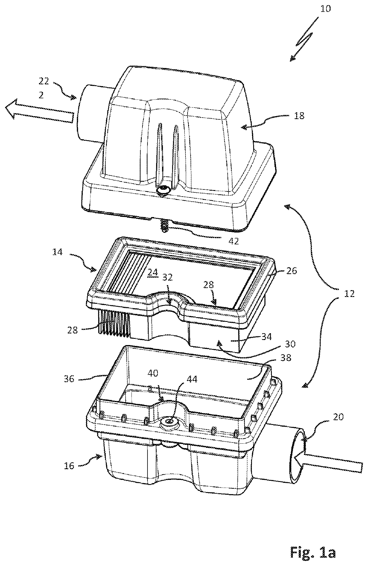
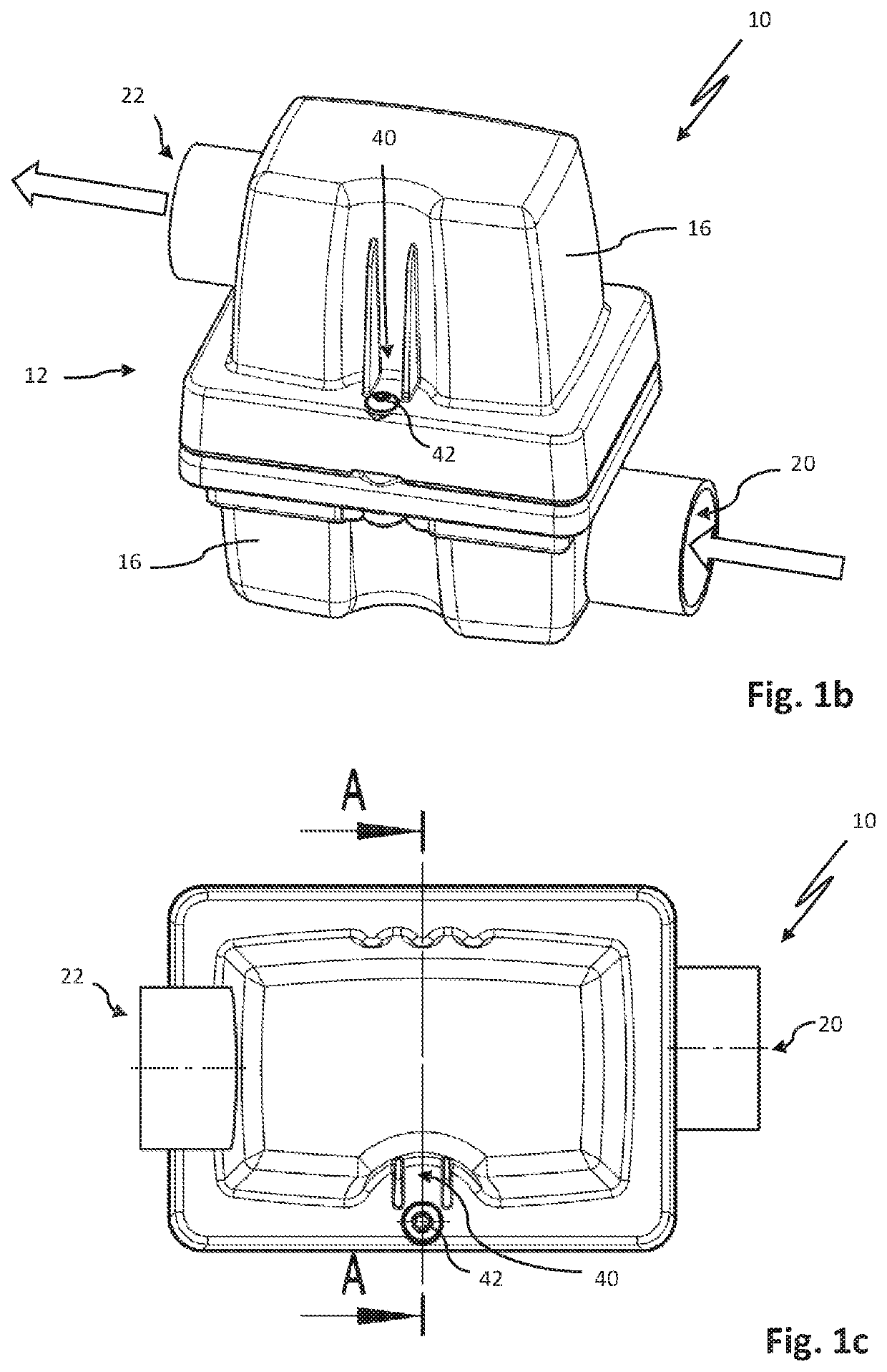
[0062]FIG. 1a shows an air filter 10 according to the invention with a filter housing 12 and with a flat air filter element 14 in a schematic exploded illustration. The filter housing 12 comprises a housing pot 16 and a housing cover 18. An inlet of the filter housing for the air to be filtered is identified at 20 and an outlet of the filter housing 12 is identified at 22. The flat air filter element 14 can be arranged between the housing pot 16 and the housing cover 18.

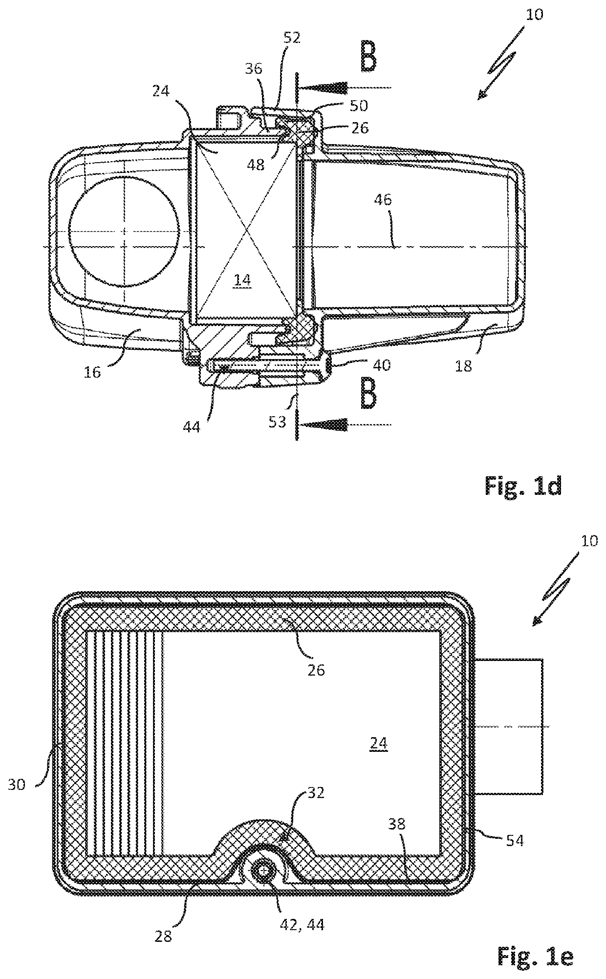
[0063]The flat air filter element 14 comprises a filter medium 24 and a sealing element 26 which is arranged circumferentially extending at the filter medium 24. The filter medium 24 is comprised of a cellulose material. The filter medium 24 is folded in a zigzag shape and is in the form of a bellows. Preferably the filter medium 24 is cut before it is folded to the bellows. The filter medium comprises end edges 28 which are preferably glued together in a water-resistant way; in particular, an end edge bond is formed...

second embodiment

[0070]FIG. 2 shows an air filter 10 with a flat air filter element 14 in an exploded illustration of its parts. The air filter 10 differs from the air filter 10 described above in connection with FIGS. 1a to 1e substantially in that the recess 32 is embodied in a corner area 54 of the flat air filter element 14. The recess 32 can be in particular embodied as an inwardly curved concave indentation of the outer contour 30 of the flat air filter element 14. As a closure element 42, a screw can be arranged in the region of the recess 32.

[0071]FIG. 3 shows a third embodiment of an air filter 10 is an exploded illustration of its parts. The third embodiment corresponds in its configuration substantially to the second embodiment according to FIG. 2. A recess 32 at the corner area 54 of the flat air filter element 14 is here embodied as a bevel. The rim section 36 of the housing pot 16 can have an inset portion 40 which is adapted to the shape of the bevel.

fourth embodiment

[0072]FIG. 4a shows an air filter 10 in an exploded illustration. As a closure element 42, a clamping spring is provided here. The recess 32 is centrally formed at a lateral edge 34 of the flat air filter element 14. The recess 32 can be wider than deep, in particular at least twice as wide as deep.

[0073]FIG. 4b shows the air filter 10 according to FIG. 4a in a cross section view at the level of the recess 32 and the clamping spring. The clamping spring engages around a lateral projection 56 of the housing pot 16 and the annular collar 52 of the housing cover 18. The clamping spring can be elastically expanded in this context. In this way, the housing pot 16 and the housing cover 18 can be clamped against each other. In this context, the sealing element 26 of the flat air filter element 14 is clamped circumferentially between the housing pot 16 and the housing cover 18. The sealing element 26 comprises the holding groove 48 that is engaged by the free rim section of the housing pot ...


PUM

PropertyMeasurementUnit
depthaaaaaaaaaa
tangential angleaaaaaaaaaa
depthaaaaaaaaaa

Abstract

A flat air filter element for an air filter has a filter medium of cellulose material and a sealing element extending circumferentially about the filter medium. Sealing element and filter medium have at least one recess at an outer contour of the flat air filter element. The sealing element has a circumferentially extending holding groove to be engaged by a housing part of a filter housing. The filter housing has a housing pot, a housing cover to cover the housing pot, and a closure element for closing the filter housing. The flat air filter element is secured in the closed state of the filter housing by circumferentially clamping the sealing element between housing pot and housing cover. The circumferentially extending holding groove of the sealing element is engaged by housing pot or housing cover. The closure element of the filter housing is arranged in the region of the recess.

Description

CROSS-REFERENCE TO RELATED APPLICATIONS[0001]This application is a continuation application of international application No. PCT / EP2017 / 059993 having an international filing date of 26 Apr. 2017 and designating the United States, the international application claiming a priority date of 27 Apr. 2016 based on prior filed German patent application No. 10 2016 005 088.8, the entire contents of the aforesaid international application and the aforesaid German patent application being incorporated herein by reference.BACKGROUND OF THE INVENTION[0002]The invention concerns a flat air filter element, in particular for an air filter in the air intake manifold of an internal combustion engine, as well as an air filter.[0003]Air filters are employed in the air intake manifold in internal combustion engines, for example, in motor vehicles, in order to remove contaminants from the combustion air to be supplied to the internal combustion engine. When the combustion air passes through a filter med...

Claims


Application Information

Patent Timeline
Patent Type & Authority Patents(United States)
IPC IPC(8): B01D46/10B01D46/42F02M35/02F02M35/024B01D46/00
CPCF02M35/02491B01D46/0005F02M35/0203F02M35/02441B01D46/10B01D46/4236B01D2279/60B01D2275/206B01D2271/02
Inventor DIRNBERGER, TIMOSCHMID, DANIELWEBER, ANDREAS
Owner MANN HUMMEL GMBH
Why Eureka
Try Eureka