Heat dissipation device and fan assembly thereof

a heat dissipation device and fan assembly technology, applied in the direction of piston pumps, semiconductor/solid-state device details, gearing, etc., can solve the problems of large impact on the efficiency of the cooling fan, increase the size of the hub, and excessive heat generated by the electronic components operating at high speed

Inactive Publication Date: 2012-12-04
FU ZHUN PRECISION IND SHENZHEN +1
View PDF11 Cites 2 Cited by
  • Summary
  • Abstract
  • Description
  • Claims
  • Application Information

AI Technical Summary

Benefits of technology

[0005]For example, U.S. Pat. No. 6,311,766 provides such a heat dissipation device for dissipating heat generated by a CPU. The heat dissipation device includes a fan, a heat sink, and a fixing device which attaches the fan to the heat sink. The fan is box-shaped, and includes a rectangular housing, a hub received in a central portion of the housing and a plurality of blades extending radially from the hub. The hub includes a circular top wall and a cylindrical sidewall extending perpendicularly from an outer periphery of the top wall. The top wall and the sidewall define a cylindrical space for accommodating a magnet and a stator therein for driving the blades to rotate in the housing. Typically, the stator includes layered yokes with stator coils wound thereon, a printed circuit board (PCB) electrically connected with the stator coils, and upper and lower insulating frames insulated the layered yokes from the stator coils. Thus, the stator has a large size, and a large space for accommodating the stator is accordingly needed, which increases a size of the hub.

Problems solved by technology

Electronic components operating at high speed generate excessive heat which must be removed efficiently to ensure normal operation.
Thus, the stator has a large size, and a large space for accommodating the stator is accordingly needed, which increases a size of the hub.
Thus, an efficiency of the cooling fan is greatly affected.

Method used


Image

  • Heat dissipation device and fan assembly thereof
  • Heat dissipation device and fan assembly thereof
  • Heat dissipation device and fan assembly thereof

Examples


first embodiment

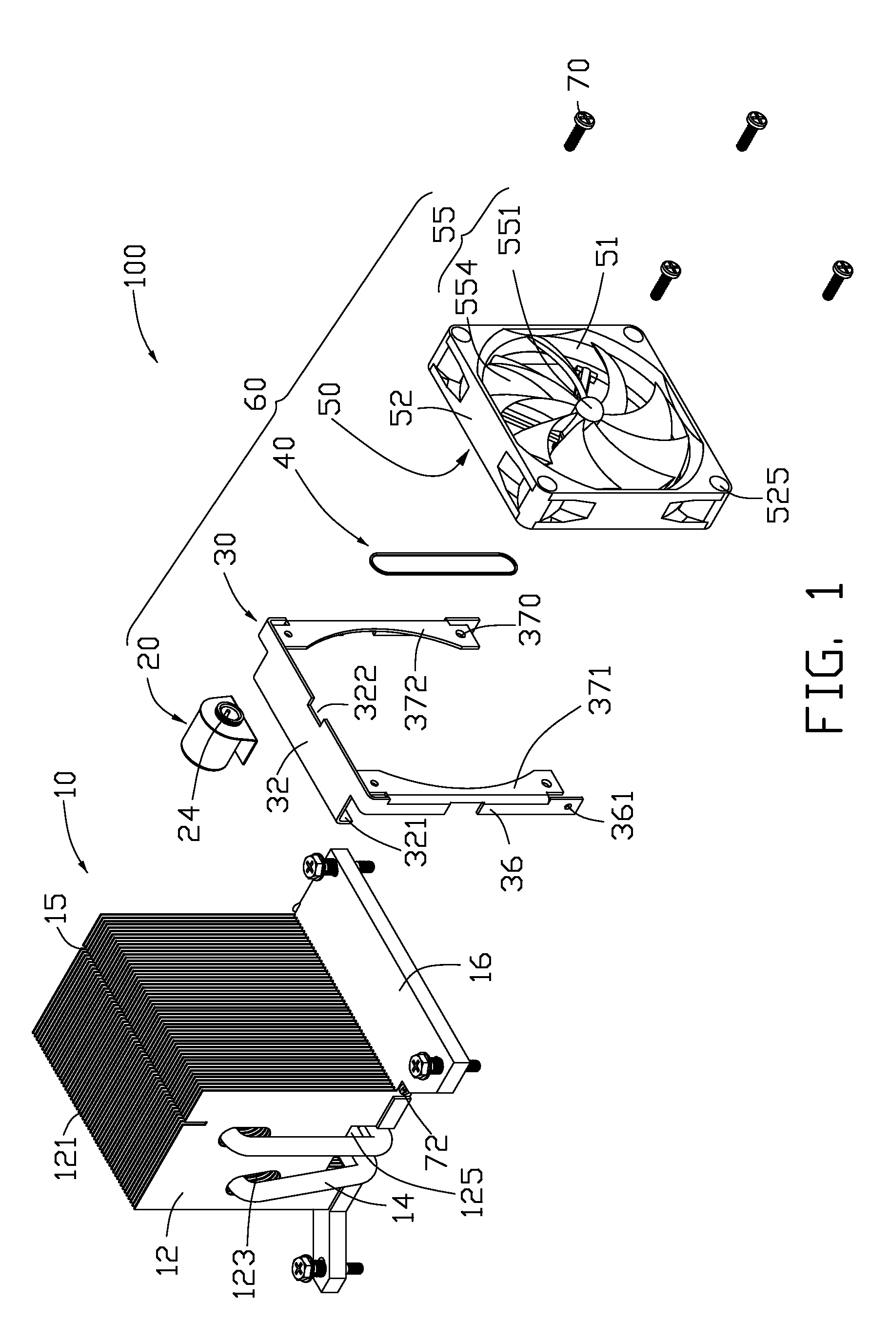
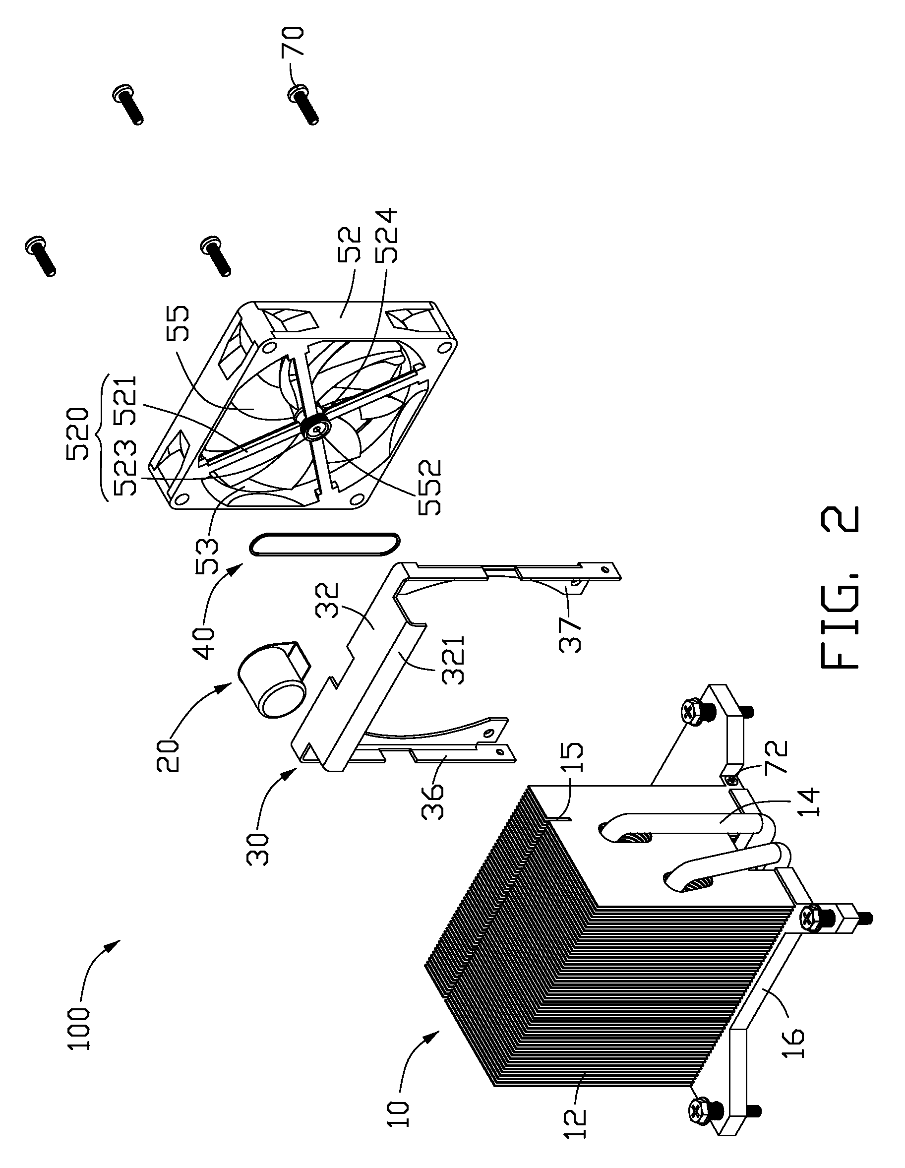
[0018]FIGS. 1-2 illustrate a heat dissipation device 100 in accordance with the disclosure. The heat dissipation device 100 is for dissipating heat generated by an electronic component (not shown). The heat dissipation device 100 includes a heat sink 10 and a fan assembly 60.

[0019]The heat sink 10 includes a heat absorbing plate 16 contacting with the electronic component, a fin unit 12 arranged on the heat absorbing plate 16 and two heat pipes 14 connecting the heat absorbing plate 16 with the fin unit 12. Each heat pipe 14 is about “U” shaped. Each of the heat pipes 14 includes a middle section, and an evaporator section and a condenser section extending perpendicularly from two opposite ends of the middle section, respectively. The fin unit 12 includes a plurality of fins 121 being paralleled to and spaced from each other. The fin unit 12 is located on one side, i.e., a left side of a top surface of the heat absorbing plate 16 with the fins 121 arranged one by one along a front-t...

third embodiment

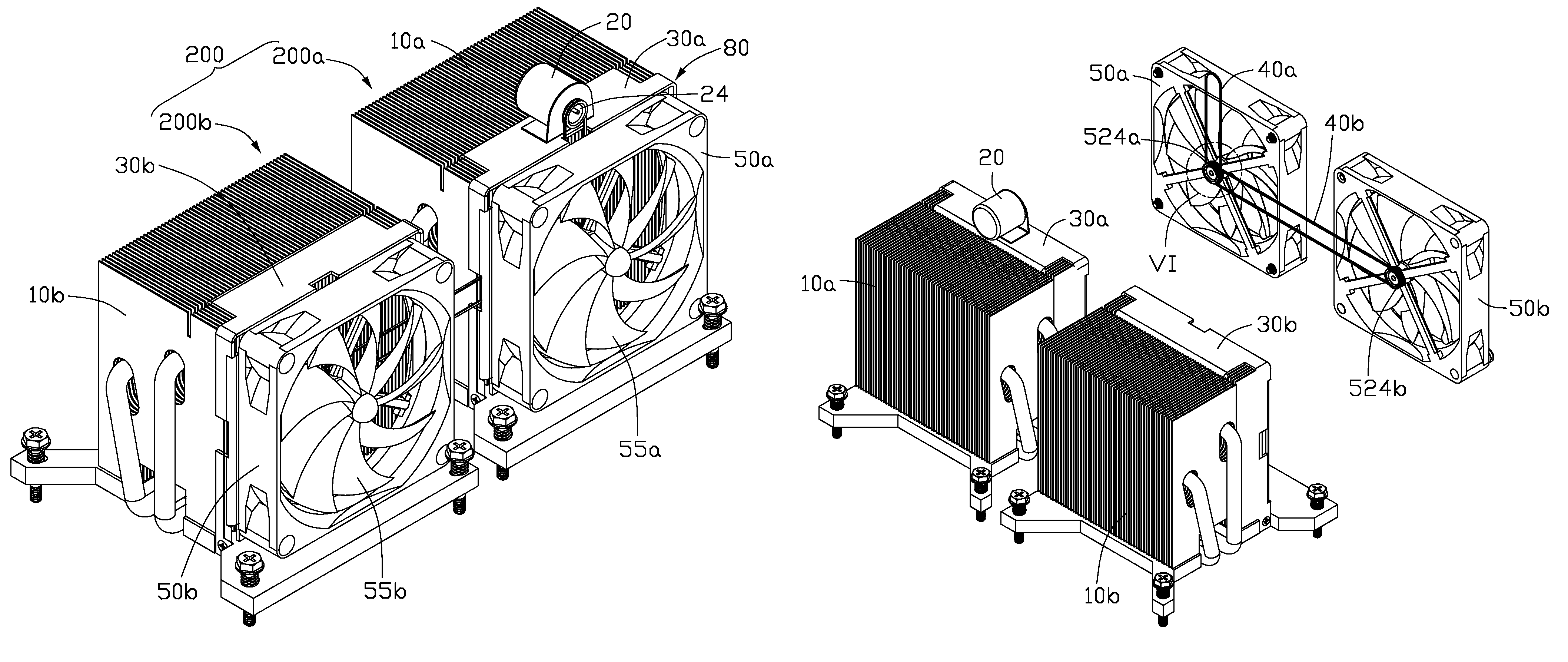
[0029]Referring to FIGS. 7-9, a heat dissipation device 300 in accordance with the disclosure is shown. The heat dissipation device 300 includes a heat sink 10c, a fixing frame 30c, upper and lower cooling fans 50c, 50d, an electric motor 20, and upper and lower belts 40c, 40d.

[0030]The heat sink 10c and the fixing frame 30c respectively has substantially the same configuration as the heat sink 10 and the fixing frame 30 of the first embodiment, only differing in that a fin unit 12c of the heat sink 10c has a height being about twice of a height of the fin unit 12 of the first embodiment, and the fixing frame 30c has a height being about twice of a height of the fixing frame 30 of the first embodiment. Each of the upper and lower cooling fans 50c, 50d has the same configuration as the cooling fan 50 the first embodiment, only differing in that a fan pulley 524c of the upper cooling fan 50c has a first pulley groove 526c and a second pulley groove 528c. The upper and lower cooling f...


PUM


Abstract

A heat dissipation device includes a heat sink, a cooling fan, an electric motor and a belt. The cooling fan includes a fan housing and an impeller. The impeller includes a hub, a plurality of fan blades and a shaft extending from the hub and having a distal end protruded out of the fan housing. A fan pulley is fixed to the distal end of the shaft. The electric motor includes a driving pulley. The belt has one end engaging with the driving pulley of the electric motor and an opposite end engaging with the fan pulley of the cooling fan. Rotation of the driving pulley of the electric motor is transferred to the fan pulley via the belt to cause the impeller to rotate.

Description

BACKGROUND[0001]1. Technical Field[0002]The disclosure relates to heat dissipation devices, and particularly to a heat dissipation device having an improved fan assembly.[0003]2. Description of Related Art[0004]Electronic components operating at high speed generate excessive heat which must be removed efficiently to ensure normal operation. Typically, a heat dissipation device attached to the electronic component provides such heat dissipation.[0005]For example, U.S. Pat. No. 6,311,766 provides such a heat dissipation device for dissipating heat generated by a CPU. The heat dissipation device includes a fan, a heat sink, and a fixing device which attaches the fan to the heat sink. The fan is box-shaped, and includes a rectangular housing, a hub received in a central portion of the housing and a plurality of blades extending radially from the hub. The hub includes a circular top wall and a cylindrical sidewall extending perpendicularly from an outer periphery of the top wall. The top...

Claims


Application Information

Patent Timeline
Patent Type & Authority Patents(United States)
IPC IPC(8): F04B35/01H05K7/20F16H7/02
CPCH01L23/4006H01L23/427H01L23/467F28D15/0275F28D15/0266F28F1/32H01L2924/0002H01L2924/00
Inventor ZHA, XIN-XIANGYU, YE-FEIDING, JUNKUO, JER-HAUR
Owner FU ZHUN PRECISION IND SHENZHEN
Why Eureka
Try Eureka