
Compactor construction

a construction and compact technology, applied in the field of compact construction, can solve the problems of transporting and disposing of such trash, and achieve the effects of minimizing the objectionable characteristics of transporting, substantial economic benefits, and minimizing the possibility

Active Publication Date: 2011-06-14
DUPERON INNOVATION LLC
View PDF22 Cites 4 Cited by
  • Summary
  • Abstract
  • Description
  • Claims
  • Application Information

AI Technical Summary

Benefits of technology

[0006]Trash compaction apparatus constructed in accordance with the presently preferred embodiment of the invention is adapted to be located in a position to receive debris extracted from a flowing stream or other source and operate continuously to compact and dewater such debris substantially simultaneously with its removal from the stream, thereby effecting substantial economies in dealing with such debris.
[0007]The compacting apparatus comprises a housing for receiving debris to be compacted, material forwarding means for forwarding the debris toward an outlet in the housing and applying a positive force on such debris as it moves in a direction to be discharged from the housing. The outlet is so constructed and arranged as to apply a resistive force on the debris as it passes through the outlet, thereby enabling the combination of the debris forwarding force and the resistive force to effect compaction of the debris as it approaches and moves through the outlet.
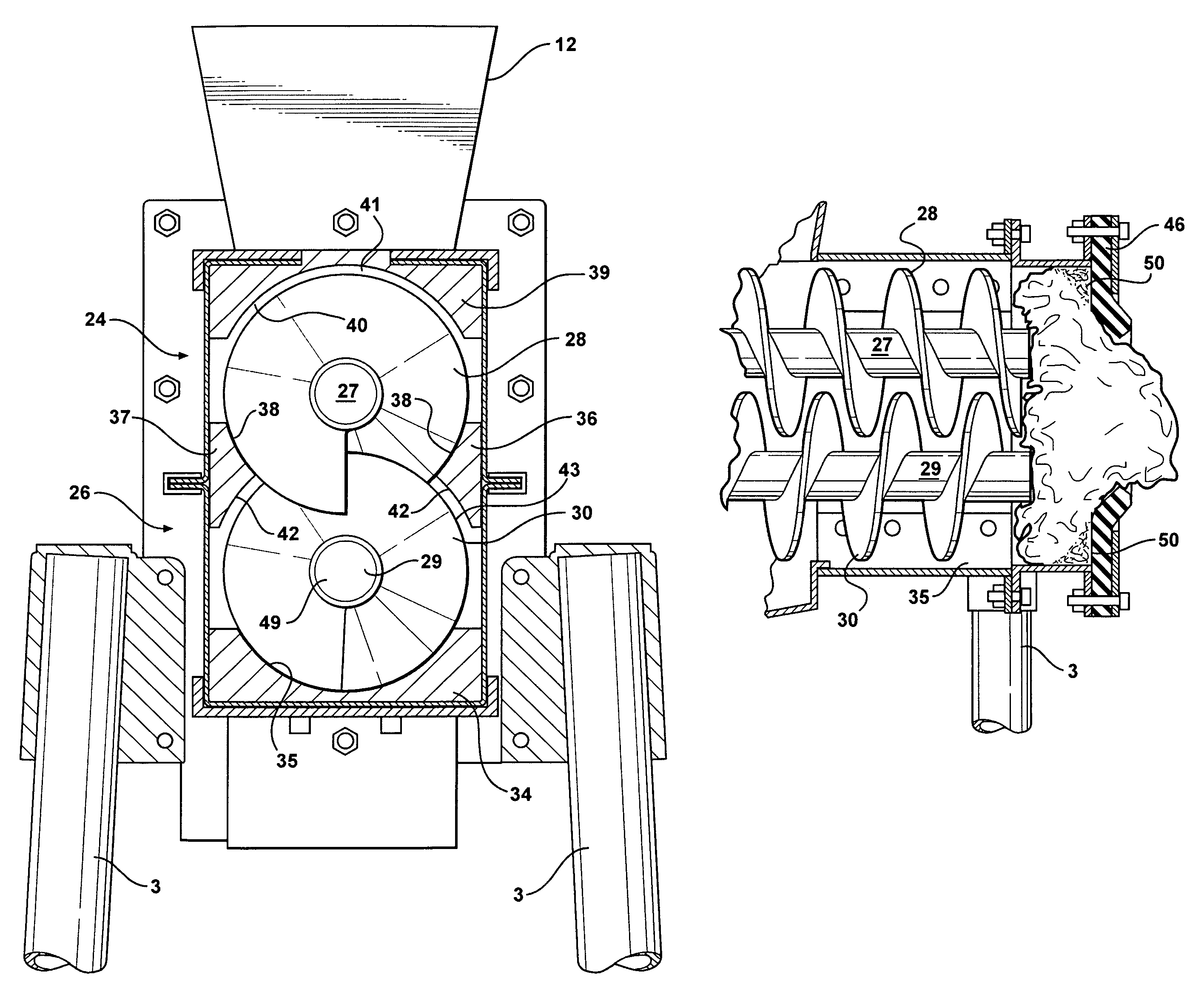
[0008]The debris forwarding means comprises a pair of vertically spaced augers each of which has a longitudinally extending shaft on which a helical vane is secured. The two shafts are driven in opposite directions by a common drive motor, but the vanes are of opposite hand so that the augers simultaneously forward debris in the housing toward the outlet. Except for the vanes being of opposite hand the augers of one embodiment are the same, whereas there may be differences in the augers of a modified embodiment. The vertical spacing between the augers is such that the vanes are interleaved with, but do not engage, one another so as to be self cleaning, thereby minimizing the possibility that debris will be able to stall either of the augers.

Problems solved by technology

Unless the trash is compacted and dewatered, the bulkiness and weight of such trash presents problems in transporting and disposing of such trash.

Method used


Image

  • Compactor construction
  • Compactor construction
  • Compactor construction

Examples


Embodiment Construction

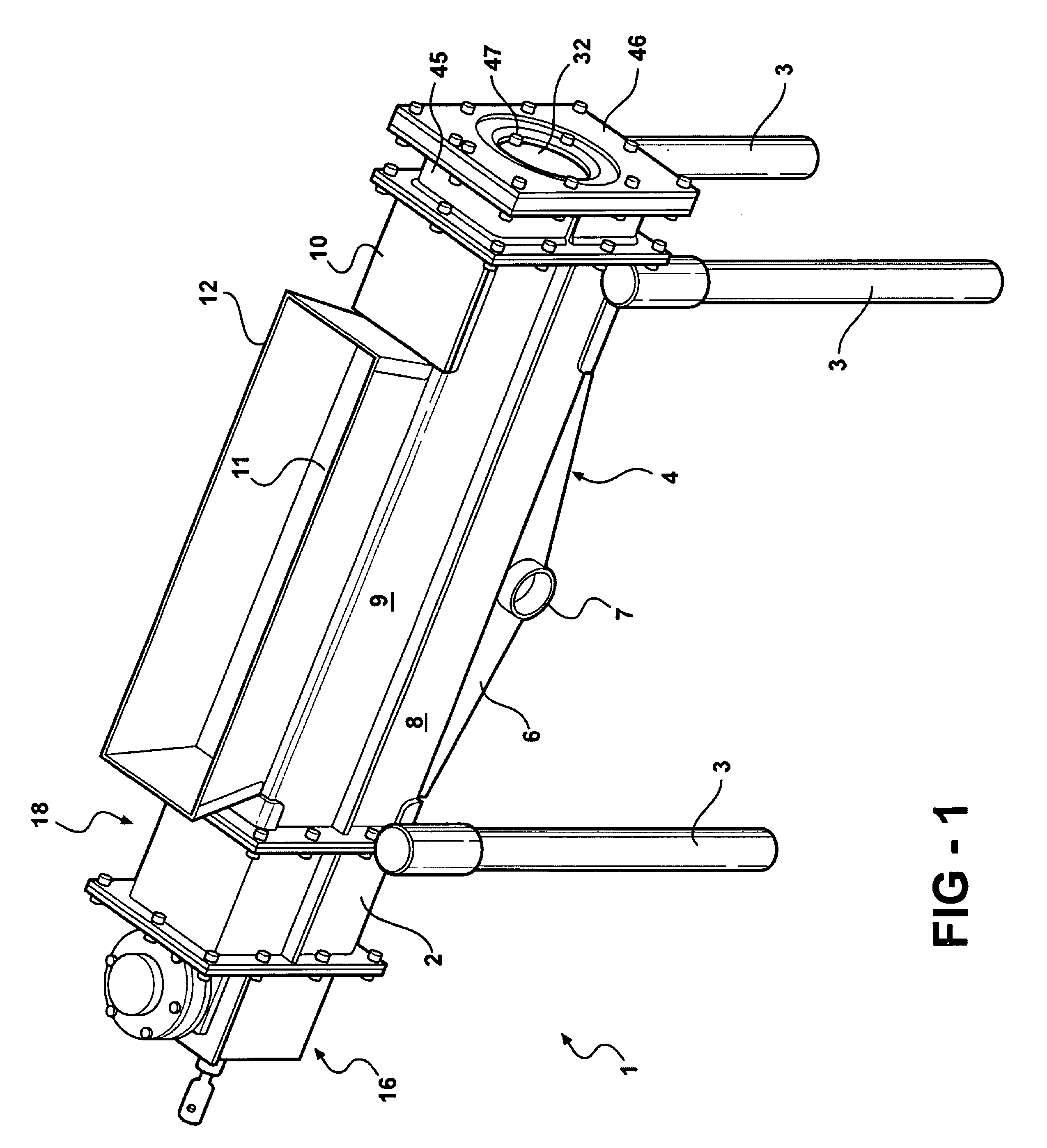
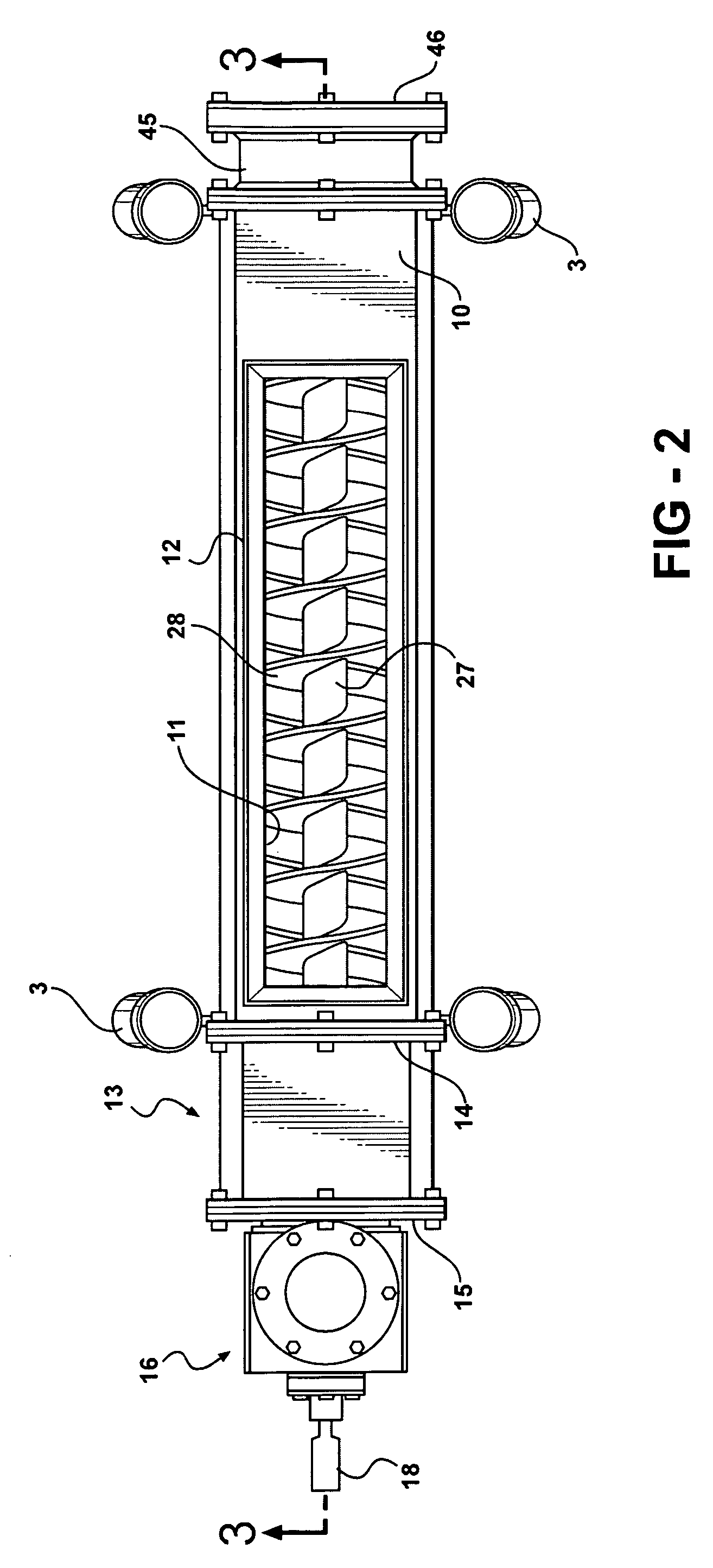
[0020]The compacting apparatus illustrated in FIGS. 1-5 is designated generally by the reference character 1 and comprises a frame 2 mounted on supporting legs 3. The frame supports a housing 4 having a downwardly converging bottom 5 and opposed side walls 6. One of the side walls has a drain opening 7. The side walls have upwardly extending extensions 8 and 9 which join a top wall 10 provided with an inlet 11. The inlet is bounded by upwardly extending guides 12 which guide debris (not shown) through the inlet 11 to the interior of the housing 4.

[0021]At one end of the housing is an enclosure 13 having end walls 14 and 15, the end wall 14 being bolted or otherwise secured to the housing 4. Bolted or otherwise secured to the end wall 15 is a support 16 for an electric drive motor (not shown) coupled to a gear reduction assembly 17 of known construction having a drive shaft 18 coupled to a driven shaft 19 which extends through a coupling 20 and a gear 21. The gear 21 meshes with a li...


PUM


Abstract

A compactor for compacting and dewatering debris comprises a housing having an inlet for enabling debris to be delivered to forwarding augers which forward the debris to a compaction chamber at the discharge end of the housing. The chamber has an outlet opening of less cross-sectional area than that of the chamber, thereby ensuring compaction of the debris as it moves toward discharge. Debris enroute to discharge may be sprayed with water to remove sludge-like substances which otherwise would cling to some types of debris.

Description

CROSS REFERENCE TO RELATED APPLICATION[0001]This application is a continuation-in-part of application Ser. No. 11 / 497,821 filed Aug. 2, 2006 now abandoned.[0002]This disclosure relates to apparatus for compacting and dewatering refuse or other compactable material.BACKGROUND OF THE APPARATUS[0003]It is common practice to install in a flowing stream debris collection apparatus for the purpose of removing trash from the stream so as to avoid such trash entering pumps, clogging screens, or otherwise interfering with or damaging downstream equipment. Examples of such trash collecting apparatus are disclosed in U.S. Pat. Nos. 4,709,804 and 5,425,875.[0004]Trash intercepted and removed from a stream typically is discharged to a collector from which it is conveyed or otherwise transported to a disposal site. Unless the trash is compacted and dewatered, the bulkiness and weight of such trash presents problems in transporting and disposing of such trash.[0005]Apparatus constructed in accorda...

Claims


Application Information

Patent Timeline
Patent Type & Authority Patents(United States)
IPC IPC(8): B30B9/16
CPCB30B9/121B30B9/18B30B9/16
Inventor DUPERON, TERRY L.
Owner DUPERON INNOVATION LLC
Learn More