Pleated single phase filter coalescer element and method

a single-phase filter and element technology, applied in the direction of filtration separation, multi-stage water/sewage treatment, separation process, etc., can solve the problems of not always removing enough free and emulsified water from the liquid to meet the ever-increasing specifications of modern industrial equipment, and complicated construction, so as to reduce flow resistance, increase coalescing area, and increase the effect of coalescing efficiency

Active Publication Date: 2011-09-13
KAYDON CUSTOM FILTRATION CORP
View PDF18 Cites 27 Cited by
  • Summary
  • Abstract
  • Description
  • Claims
  • Application Information

AI Technical Summary

Benefits of technology

[0010]Yet another aspect of the present invention is to provide a filter coalescer having substantially increased coalescing area which provides greater efficiency in removing water from the industrial liquid with reduced flow resistance. The filter coalescer also has improved filtering effectiveness to remove a high percentage of particulate from the industrial liquid. The filter coalescer has a single stage construction which eliminates the need for a separate pre-filter and bun type coalescer, along with a compact shape which permits use of the same in existing filtration equipment, while providing improved filtration performance. The filter coalescer has a lightweight construction and is corrosion resistant to provide a long operating life. The filtering coalescer reduces component wear, increases oil life, reduces maintenance and minimizes machine downtime, thereby providing substantial economic benefits to the user. The filter coalescer has an uncomplicated design, reduced manufacturing costs, and is particularly well adapted for the proposed use.

Problems solved by technology

While such devices are generally effective, they have a rather complicated construction, provide significant resistance to fuel flow through the system, and do not always remove enough free and emulsified water from the liquid to meet the ever-increasing specifications required by modern industrial equipment.

Method used


Image

  • Pleated single phase filter coalescer element and method
  • Pleated single phase filter coalescer element and method
  • Pleated single phase filter coalescer element and method

Examples


Embodiment Construction

[0020]For purposes of description herein, the terms “upper”, “lower”, “right”, “left”, “rear”, “front”, “vertical”, “horizontal” and derivatives thereof shall relate to the invention as oriented in FIG. 1. However, it is to be understood that the invention may assume various alternative orientations and step sequences, except where expressly specified to the contrary. It is also to be understood that the specific devices and processes illustrated in the attached drawings, and described in the following specification, are simply exemplary embodiments of the inventive concepts defined in the appended claims. Hence, specific dimensions and other physical characteristics relating to the embodiments disclosed herein are not to be considered as limiting, unless the claims expressly state otherwise.

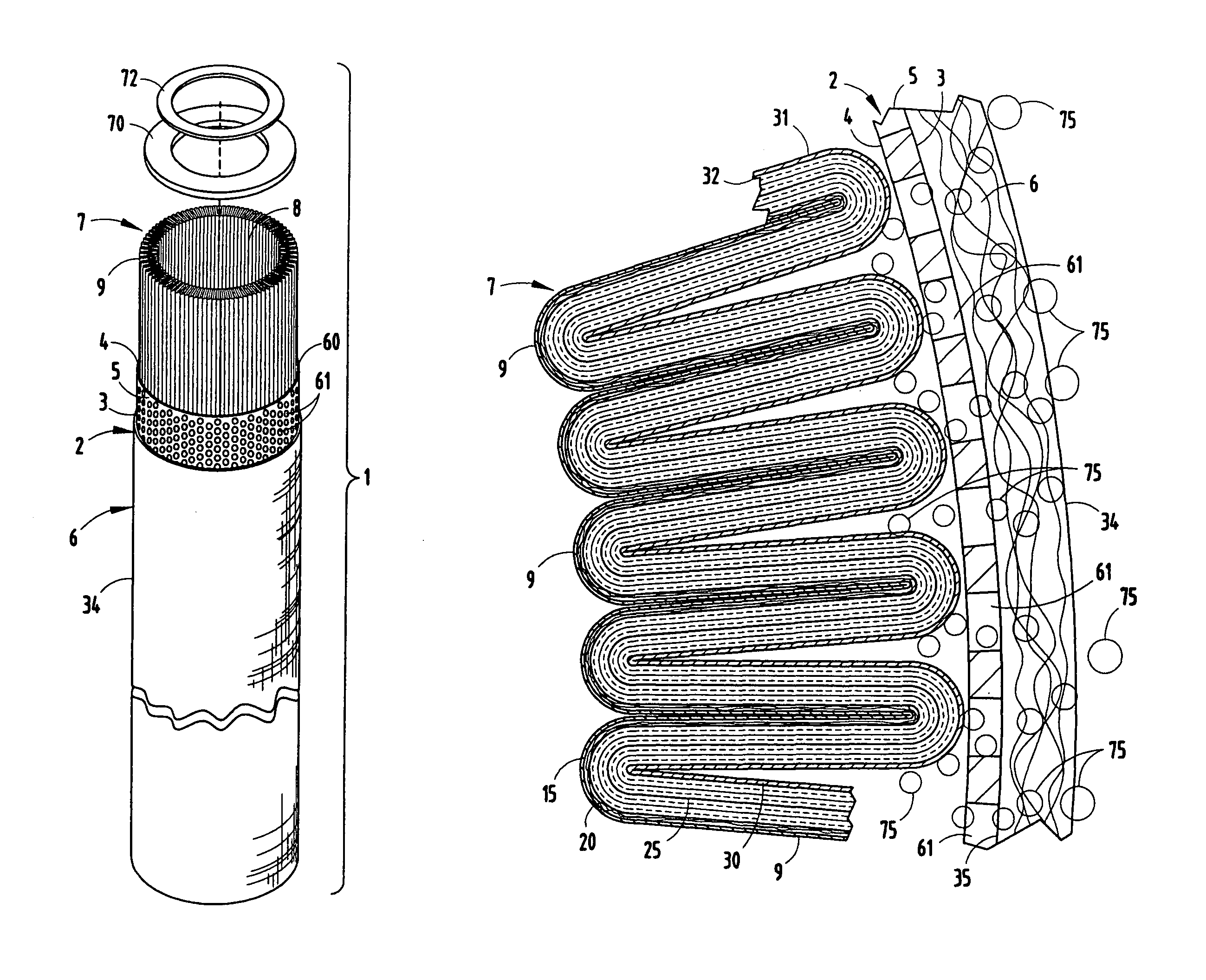
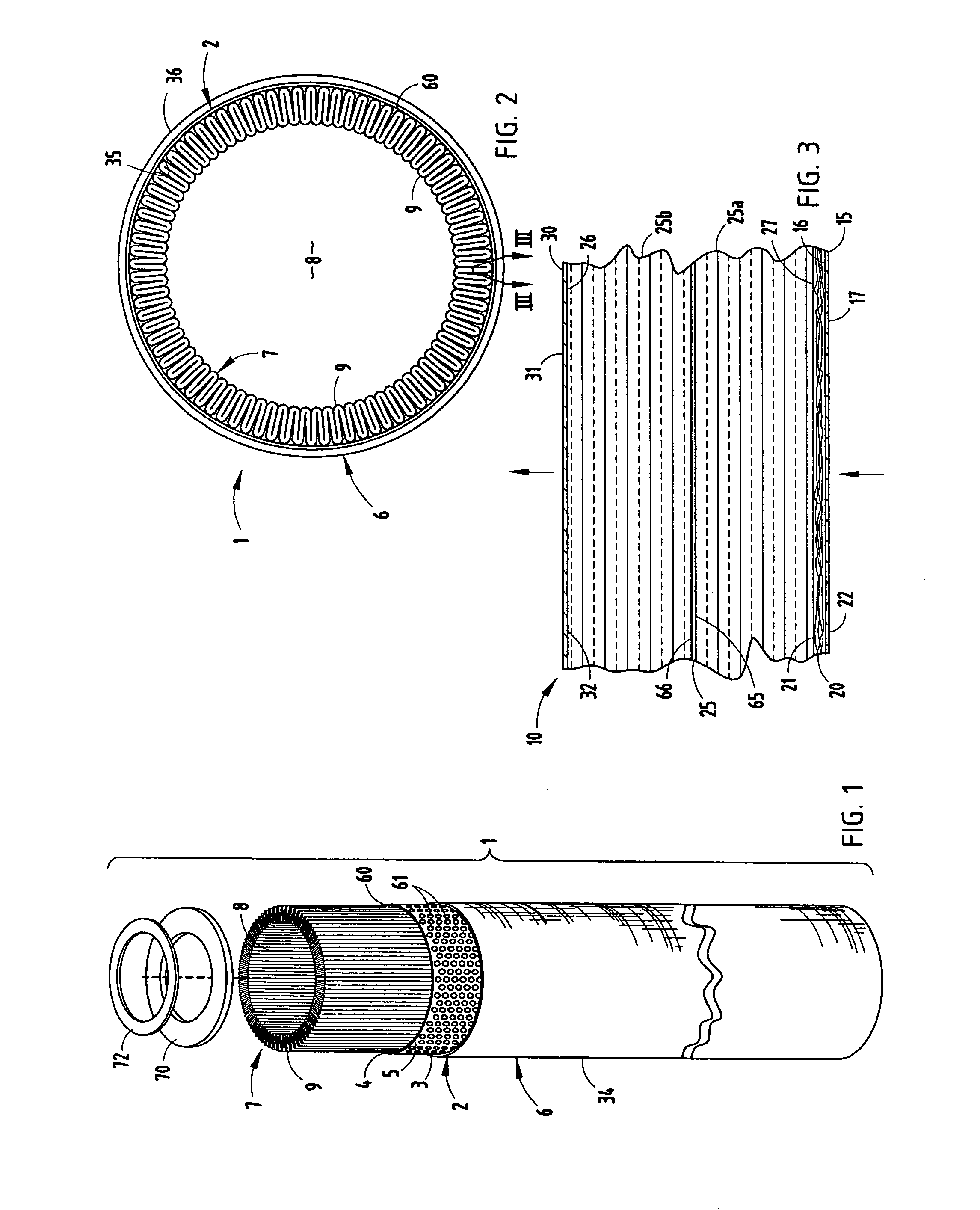
[0021]The reference numeral 1 (FIG. 1) generally designates a filter coalescer cartridge or element embodying the present invention. Filter coalescer element 1 is generally a liquid / liquid separ...


PUM

PropertyMeasurementUnit
thicknessaaaaaaaaaa
diameteraaaaaaaaaa
diameteraaaaaaaaaa

Abstract

A filter coalescer element for oil based industrial fuels includes a rigid, porous support tube, and a hydrophobic drainage layer covering the outer surface of the same. A single phase, dual function combination water coalescer and particle filter pleat block is positioned in the support tube, and is formed from a multilayer material having a first porous support layer, a synthetic microfiber layer, a synthetic fiber media layer and a second porous support layer. As the fluid passes through the pleat block, solid particles are physically filtered therefrom, and water is coalesced into droplets which pass from the pleats directly through the support tube and directly into the drainage layer, where the droplets grow into a size sufficient that they fall under gravity to the bottom of the element for collection.

Description

BACKGROUND OF THE DISCLOSURE[0001]The present invention relates to filtration and coalescer devices, and in particular to a pleated single phase filter coalescer element and method for removing contaminates from lubricants, fuels and other oil based industrial liquids.[0002]Filtering and coalescing devices for oil based industrial fluids, such as petrochemicals in the nature of gasoline, diesel fuel, turbine oil, gear oil, hydraulic fluid, lubricating oil, etc., organic and / or vegetable oils, fuels, etc., as well as synthetic based lubricants and the like, are well known in the art. Contaminants, including particulate, water, and other foreign substances, must be removed from these industrial fluids to ensure proper long term operation and protection of the associated equipment. For example, to achieve long term, predictable and profitable performance from turbines and turbine driven equipment, the lubrication must be both water-free and particulate-free. Oil conditioning systems ar...

Claims


Application Information

Patent Timeline
Patent Type & Authority Patents(United States)
IPC IPC(8): B01D29/07B01D27/06B01D29/00B01D27/00
CPCB01D36/003B01D39/1623Y10T29/49826Y10S210/05B01D2239/065
Inventor ELLIS, JASON A.GARRETT, RON J.
Owner KAYDON CUSTOM FILTRATION CORP
Why Eureka
Try Eureka