Hydraulic hybrid power system

a hybrid power system and hydropower technology, applied in the direction of propulsion parts, propulsion using engine-driven generators, transportation and packaging, etc., can solve the problems of system cost and general impracticality of proposals, and achieve the effect of low cost and large improvement in vehicle fuel economy

Inactive Publication Date: 2010-06-03
MENDLER EDWARD CHARLES
View PDF11 Cites 33 Cited by
  • Summary
  • Abstract
  • Description
  • Claims
  • Application Information

AI Technical Summary

Benefits of technology

[0007]According to the present invention a pump is driven by one or more wheels of a hydraulic hybrid vehicle during braking. The hydraulic hybrid vehicle has a heat engine such as a reciprocating piston internal combustion engine. The inertial energy of the vehicle powers the hydraulic pump during braking of the vehicle, and the pump pumps a liquid into a hydraulic accumulator that stores the fluid at its elevated pressure. When additional power is required by the vehicle, the liquid is released into a heat exchanger that transfers heat from the exhaust gas of the heat engine to the liquid causing at least a portion of the liquid to become gaseous. The heated fluid is then fed into an expander that generates shaft power by expanding the pressurized and heated gaseous and / or liquid fluid mixture. The preferred embodiment of the present invention operates under the Rankine cycle or steam engine cycle where the liquid compression function is performed using power from regenerative braking, and the liquid heating and vaporization function is performed using exhaust gas waste heat. The present invention shows potential for more than tripling the regenerative braking power of hydraulic hybrid vehicles, thereby providing a large improvement in vehicle fuel economy. According to the present invention, upgrading the hydraulic hybrid system to include a Rankine bottoming cycle can be accomplished at a relatively low cost because only a few new components are required.

Problems solved by technology

Proposals have been made for further increasing the efficiency of hybrid electric vehicles, however these proposals are generally impractical because they add cost to an already expensive system.
The system is very costly due to the added cost of the Rankine cycle engine to the already costly hybrid electric powertrain.

Method used


Image

  • Hydraulic hybrid power system
  • Hydraulic hybrid power system
  • Hydraulic hybrid power system

Examples


Embodiment Construction

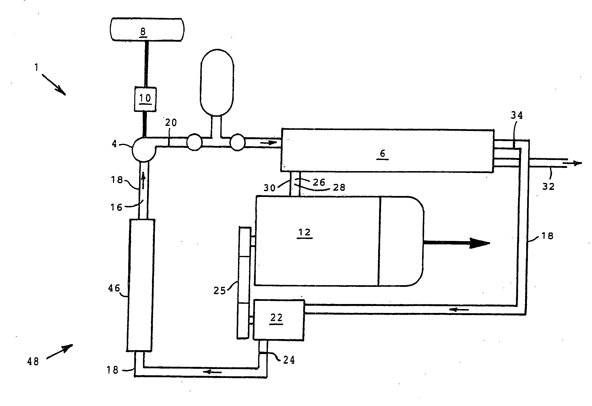
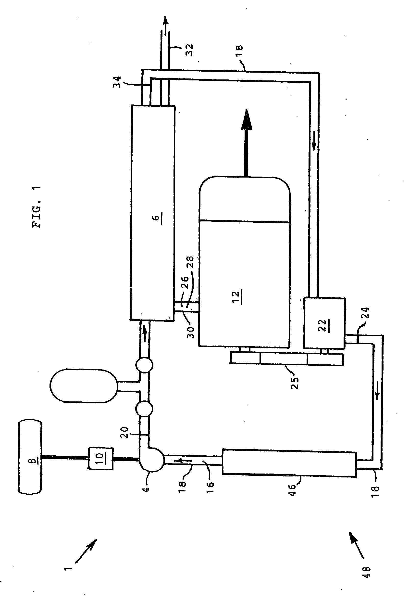
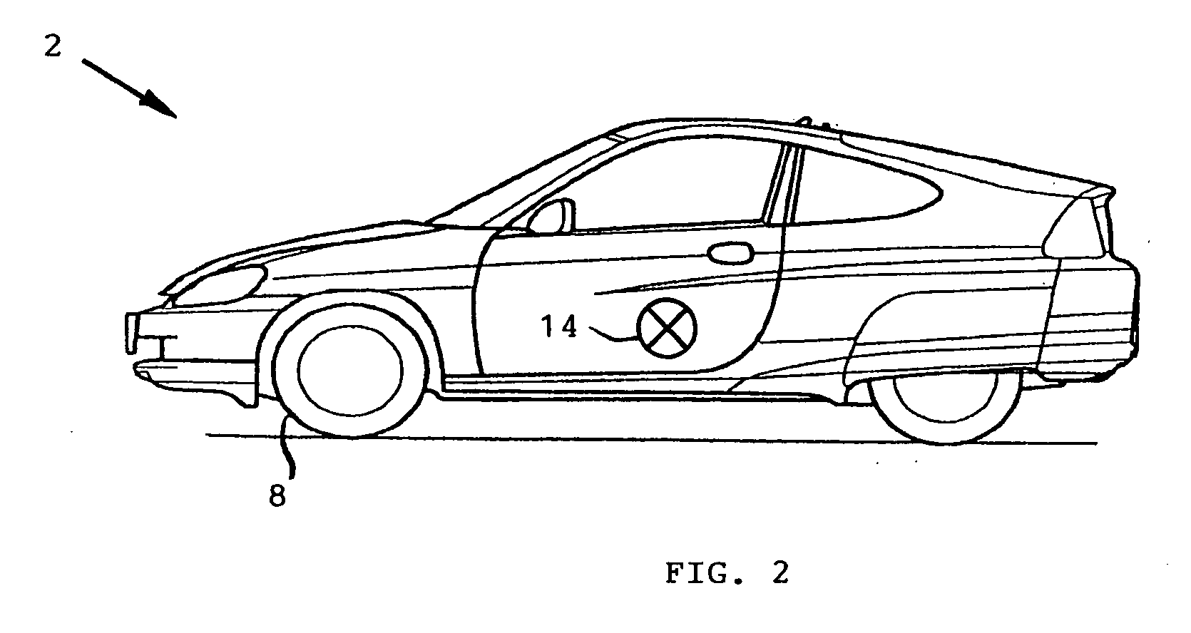
[0014]FIGS. 1 and 2 are intended to schematically illustrate a hydraulic power system 1 for a hydraulic hybrid vehicle 2 having a compressor 4 and a heat exchanger 6 according to the present invention.

[0015]According to the preferred embodiment of the present invention, compressor 4 is mechanically driven by one or more wheels 8 through an optional coupling 10. Hybrid hydraulic vehicle 2 has an engine 12 and a vehicle inertia or inertial mass 14. Inertial mass 14 is schematically illustrated in FIG. 2

[0016]Referring now to FIGS. 1 and 2, hydraulic hybrid vehicle 2 includes a working fluid 16 and hydraulic piping 18 for transporting working fluid 16 through the hydraulic power system. Compressor 4 is positioned and used for pressurizing working fluid 16. Compressor 4 is also rotatably coupled to one or more wheels 8 for converting vehicle inertia 14 into an increase in pressure or an increase in specific internal energy of the working fluid 16 during braking of vehicle 2. Specific in...


PUM


Abstract

According to the present invention a pump is driven by one or more wheels of a hydraulic hybrid vehicle during braking. The inertial energy of the vehicle powers the pump during braking of the vehicle, and the pump pumps a hydraulic liquid into an hydraulic accumulator that stores the fluid at its elevated pressure. When additional power is required by the vehicle, the liquid is released into a heat exchanger that transfers heat from the exhaust gas of the engine to the liquid causing at least a portion of the liquid to become gaseous. The heated fluid is then fed into an expander that generates shaft power by expanding the pressurized and heated gaseous and / or liquid fluid mixture. The preferred embodiment of the present invention operates under the Rankine cycle or steam engine cycle where the liquid compression function is performed using power from regenerative braking, and the liquid heating and vaporization function is performed using exhaust gas waste heat. The present invention shows potential for more than tripling the regenerative braking power of hydraulic hybrid vehicles, thereby providing a large improvement in vehicle fuel economy.

Description

[0001]This application relates to Provisional Application 60 / 931,965 having a filing date of May 24, 2007.BACKGROUND OF THE INVENTION[0002]Hydraulic hybrid drive systems for improving vehicle fuel economy have been known for some time. These hydraulic hybrid systems capture energy normally wasted during braking and re-use the same energy to accelerate the vehicle at a later time, thereby reducing fuel consumption. Hydraulic hybrid vehicles typically include a pump that is driven by one or more of the vehicles wheels during braking. During braking the pump pumps a liquid hydraulic fluid into a hydraulic accumulator. The hydraulic accumulator is typically partially filled with nitrogen, the nitrogen being held separate from the liquid hydraulic fluid by a bladder or other separation means. The nitrogen acts as a spring. During braking the pump compresses the nitrogen spring by pumping liquid hydraulic fluid into the hydraulic accumulator. At a later time when power is required for acc...

Claims


Application Information

Patent Timeline
Patent Type & Authority Applications(United States)
IPC IPC(8): B60K6/12
CPCB60K3/00B60K6/12B60K6/485Y02T10/6208Y02T10/6226B60L1/02Y02T10/70B60L11/14B60L2210/40B60L2240/445B60L2270/12Y02T10/7077Y02T10/7241B60L7/26B60L50/16Y02T10/62Y02T10/7072Y02T10/72
Inventor MENDLER, EDWARD CHARLES
Owner MENDLER EDWARD CHARLES
Why Eureka
Try Eureka