
System And Method For Controlling A Matrix Of Light Emitting Diodes And Light Provided Therewith

a technology of light-emitting diodes and matrixes, which is applied in the direction of electric variable regulation, process and machine control, instruments, etc., can solve the problems of bulb failure and replacement, relative high energy consumption, and relatively short life of bulbs

Inactive Publication Date: 2010-01-21
ELUMEN LIGHTING NETWORKS
View PDF12 Cites 34 Cited by
  • Summary
  • Abstract
  • Description
  • Claims
  • Application Information

AI Technical Summary

Benefits of technology

[0005]An object of the present invention is therefore to provide an improved system and method for controlling a matrix of light emitting diodes.
[0007]According to the present invention, there is provided a method and system for controlling a matrix of light emitting diodes in a streetlight or the like. The present method and system allows maximizing the energy savings. Moreover, it allows controlling current flowing in the diodes so as to obtain the maximum flux of light with the minimum energy and also allows meeting all safety, EMI, reliability and robustness requirements.
[0008]For example, a streetlight provided with a matrix of light emitting diodes and a system for controlling such a matrix according to the present invention provides significant energy savings and a useful life that is more then 10 times higher compared to the conventional high pressure sodium or mercury lamps. One major advantage is that the light efficiency is much higher. Therefore a streetlight according to the present invention generates a large economy of energy in the order of 80% compared to streetlights provided with bulb lamps. A second advantage is the longer life of the diodes matrix. A high pressure sodium bulb has only a few years of useful life while the light emitting diode has more then 20 years of useful life. This allows significantly reducing the maintenance cost, reducing the scrap and increasing the road safety.
[0011]a controller for connecting to both the input line and to the power converter; the controller including a voltage sensor for sensing the input voltage and a pre-regulator i) for receiving the operating current, the input current and the input voltage, ii) for biasing the operating current towards a target current, and iii) for regulating the power converter to cause the input current to follow the shape and frequency of the input voltage, yielding a unity power factor and minimizing the input current harmonic distortion.
[0017]controller means for connecting to both the input line and to the converter means i) for receiving the operating current, the input current and the input voltage, ii) for biasing the operating current towards a target current, and iii) for regulating the converter means to cause the input current to follow the shape and frequency of the input voltage, yielding a unity power factor and minimizing the input current harmonic distortion.
[0022]converting the input line voltage into a direct current (D.C.) output voltage for powering up the LEDs, yielding an operating current through the LEDs, by forcing the input current to follow the shape and frequency of the input voltage, yielding a unity power factor and minimizing the input current harmonic distortion;

Problems solved by technology

A first disadvantage is the relatively high energy consumption.
Another one is the relatively short life of the bulb.
Indeed, after a few years of operation the bulb fails and needs to be replaced.
However, the power controlling of current LED matrix in streetlight has been found inefficient, resulting in lost of energy and of light flux for a given input power consumption.

Method used


Image

  • System And Method For Controlling A Matrix Of Light Emitting Diodes And Light Provided Therewith
  • System And Method For Controlling A Matrix Of Light Emitting Diodes And Light Provided Therewith
  • System And Method For Controlling A Matrix Of Light Emitting Diodes And Light Provided Therewith

Examples


Embodiment Construction

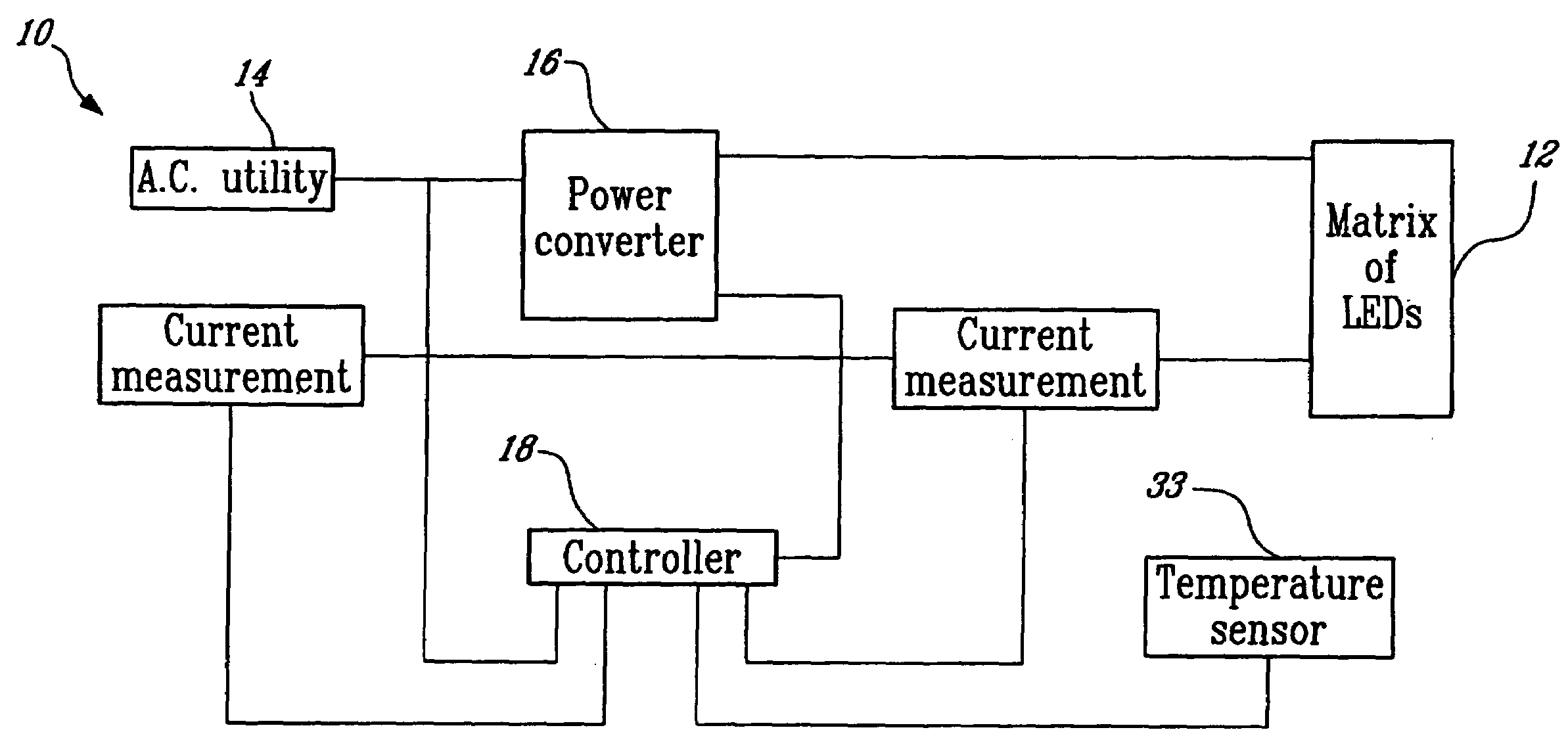
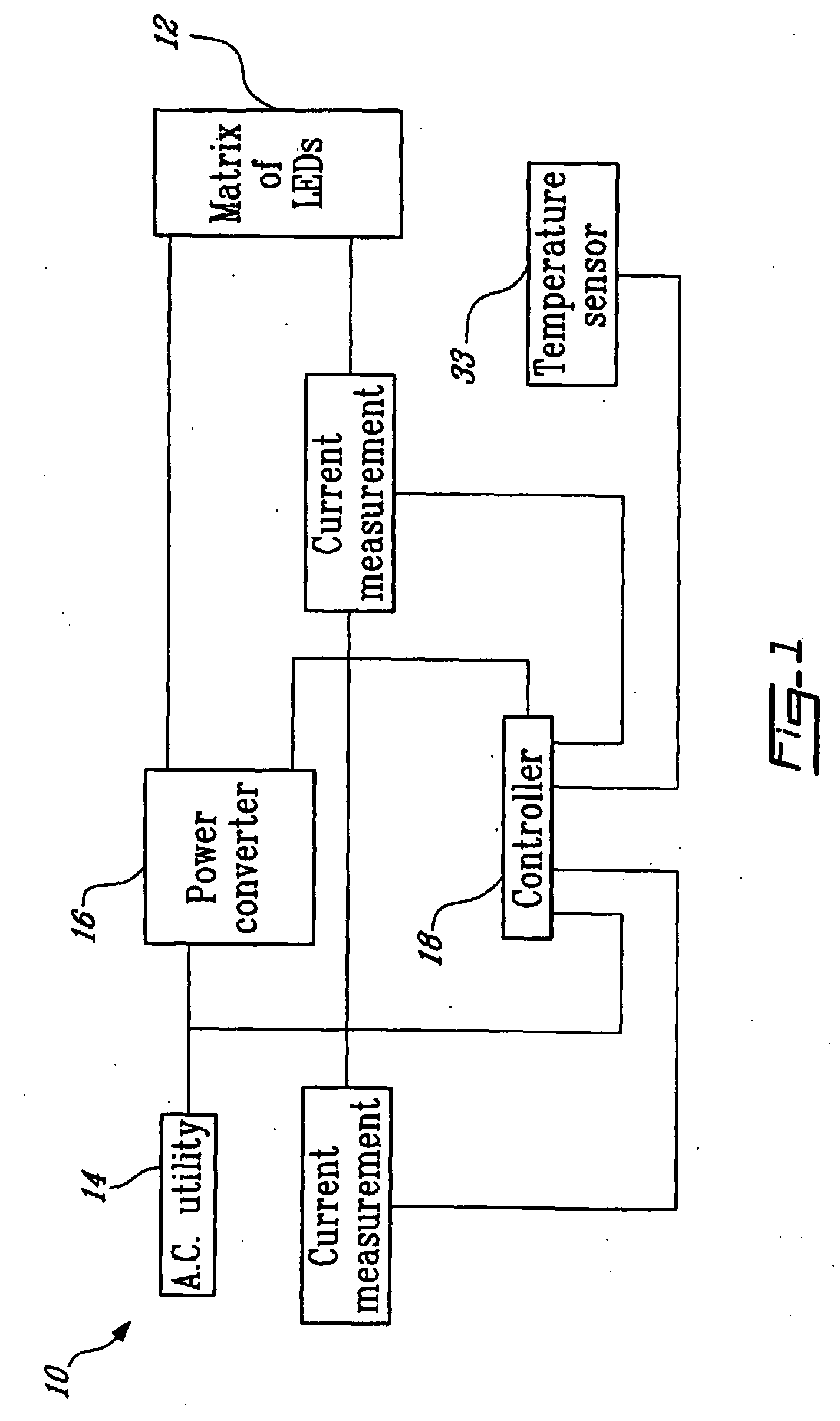
[0037]A streetlight unit 10 according to a first illustrative embodiment of the present invention will now be described with reference to FIG. 1 of the appended drawings.

[0038]The streetlight unit 10 comprises a matrix of light emitting diodes (LEDs)12 connected to the A.C. (alternating current) utility network 14 via a power converter 16, and a controller 18 for the power converter 16.

[0039]The matrix of LEDs 12 includes a combination of diodes connected in series and in parallel (not shown). This connection arrangement of diodes provides a significant improvement to the reliability and life of the streetlight 10 compare with a conventional streetlight provided with a matrix of LEDs. Indeed, the parallel connection of the diodes (for example 2 to 20) assures that even if one diode is failing short or open, the remaining matrix is not affected by the failure; the streetlight 10 can still operate, with only a small degradation of luminescence. The streetlight 10 can however operate b...


PUM


Abstract

A system and method for controlling a matrix of light emitting diodes (LED) connected to an input line comprises a power converter for connecting to the matrix of LEDs and to the input line therebetween and for receiving from the input line an input current and an input voltage characterized by a shape and a frequency and for providing a direct current (D.C.) output for powering up the LEDs, yielding an operating current through the LEDs. The power converter includes a first current sensor for sensing the input current and a second current sensor for sensing the operating current. The system further comprises a controller for connecting to both the input line and to the power converter. The controller includes a voltage sensor for sensing the input voltage and a pre-regulator i) for receiving the operating current, the input current and the input voltage, ii) for biasing the operating current towards a target current value, and iii) for regulating the power converter to cause the input current to follow the shape and frequency of the input voltage, yielding a unity power factor and minimizing the input current harmonic distortion. The present method and system allows maximizing the energy savings, controlling current flowing in the diodes so as to obtain the maximum flux of light with the minimum energy and also allows meeting all safety, EMI, reliability and robustness requirements.

Description

FIELD OF THE INVENTION[0001]The present invention relates to streetlights or the like provided with a matrix of light emitting diodes. More specifically, the present invention is concerned with a system and method for controlling such matrix.BACKGROUND OF THE INVENTION[0002]The conventional streetlight, provided with metal halide, mercury or sodium filled bulb suffers from few disadvantages. A first disadvantage is the relatively high energy consumption. Another one is the relatively short life of the bulb. Indeed, after a few years of operation the bulb fails and needs to be replaced.[0003]Matrices of light emitting diodes (LEDs) have been introduced in streetlights as a replacement solution to the conventional bulbs. However, the power controlling of current LED matrix in streetlight has been found inefficient, resulting in lost of energy and of light flux for a given input power consumption.[0004]More efficient system and method for controlling a matrix of light emitting diodes a...

Claims


Application Information

Patent Timeline
Patent Type & Authority Applications(United States)
IPC IPC(8): H05B41/36H05B44/00
CPCH05B33/0815Y02B20/347H05B33/0851Y02B20/30H05B45/18H05B45/385H05B45/38
Inventor CHAFFAI, RACHIDDUGUAY, LOUIS
Owner ELUMEN LIGHTING NETWORKS
Learn More