Assembly of a labyrinthe seal support on a turbine machine rotor

a technology of labyrinth seal and turbine machine, which is applied in the direction of screws, forging/pressing/hammering apparatus, liquid fuel engines, etc., can solve the problem of fretting and the risk of cracking, and achieve the effect of less labor

Active Publication Date: 2011-06-21
SN DETUDE & DE CONSTR DE MOTEURS DAVIATION S N E C M A
View PDF2 Cites 2 Cited by
  • Summary
  • Abstract
  • Description
  • Claims
  • Application Information

AI Technical Summary

Benefits of technology

[0010]Another object is also to develop a solution which is less onerous both as regards operating costs as well as excess engine weight.

Problems solved by technology

Indeed, tightening conditions induce a risk of starting a crack by fretting, at the edges of a free extraction hole.

Method used


Image

  • Assembly of a labyrinthe seal support on a turbine machine rotor
  • Assembly of a labyrinthe seal support on a turbine machine rotor
  • Assembly of a labyrinthe seal support on a turbine machine rotor

Examples


Embodiment Construction

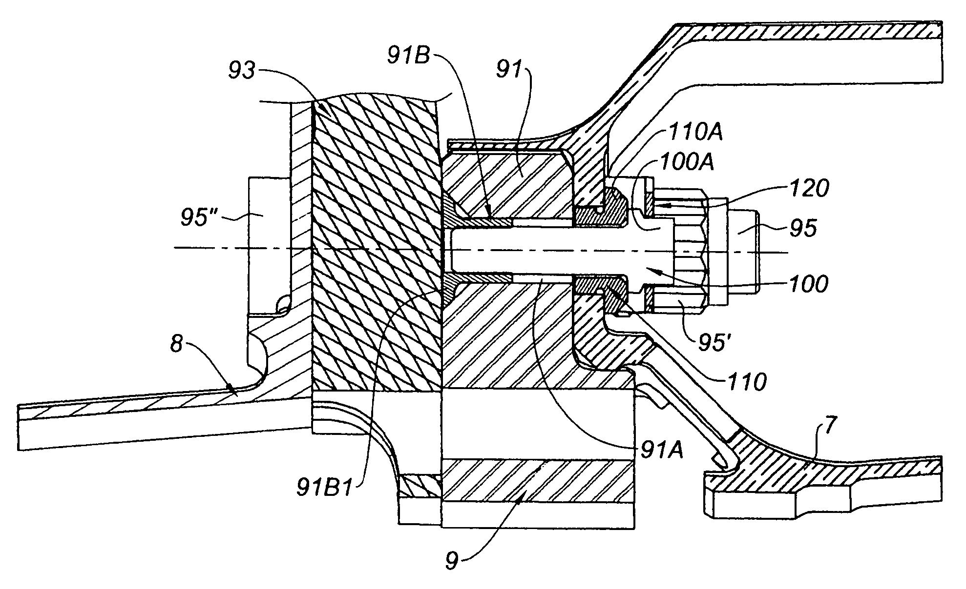
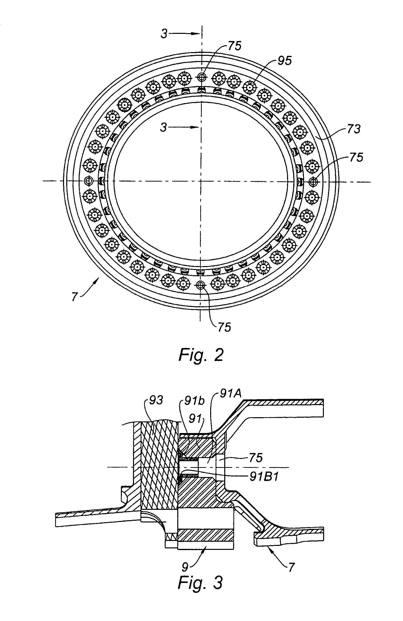
[0020]Compared with FIG. 3, FIG. 4 shows the solution of the invention with the incorporation a tightening screw 100. The upstream portion will be seen of the annular support for the rear labyrinth seal 7 with the radial part 73 resting against the flange 91 of the engine shaft 9. The support 7 is held by bolts of which, on the one hand the nut 95′ can be seen of the bolt 95 in the immediate vicinity of the extraction hole 91A and, on the other hand the head 95″. The nuts also ensure that the front labyrinth seal carrier is held in place. The radial blades of the labyrinth seal 71 are also not visible in this figure.

[0021]In order to ensure, according to the invention, that this part of the ring is tightened against the flange 91, tightening screws 100 are incorporated in the extraction holes 91A.

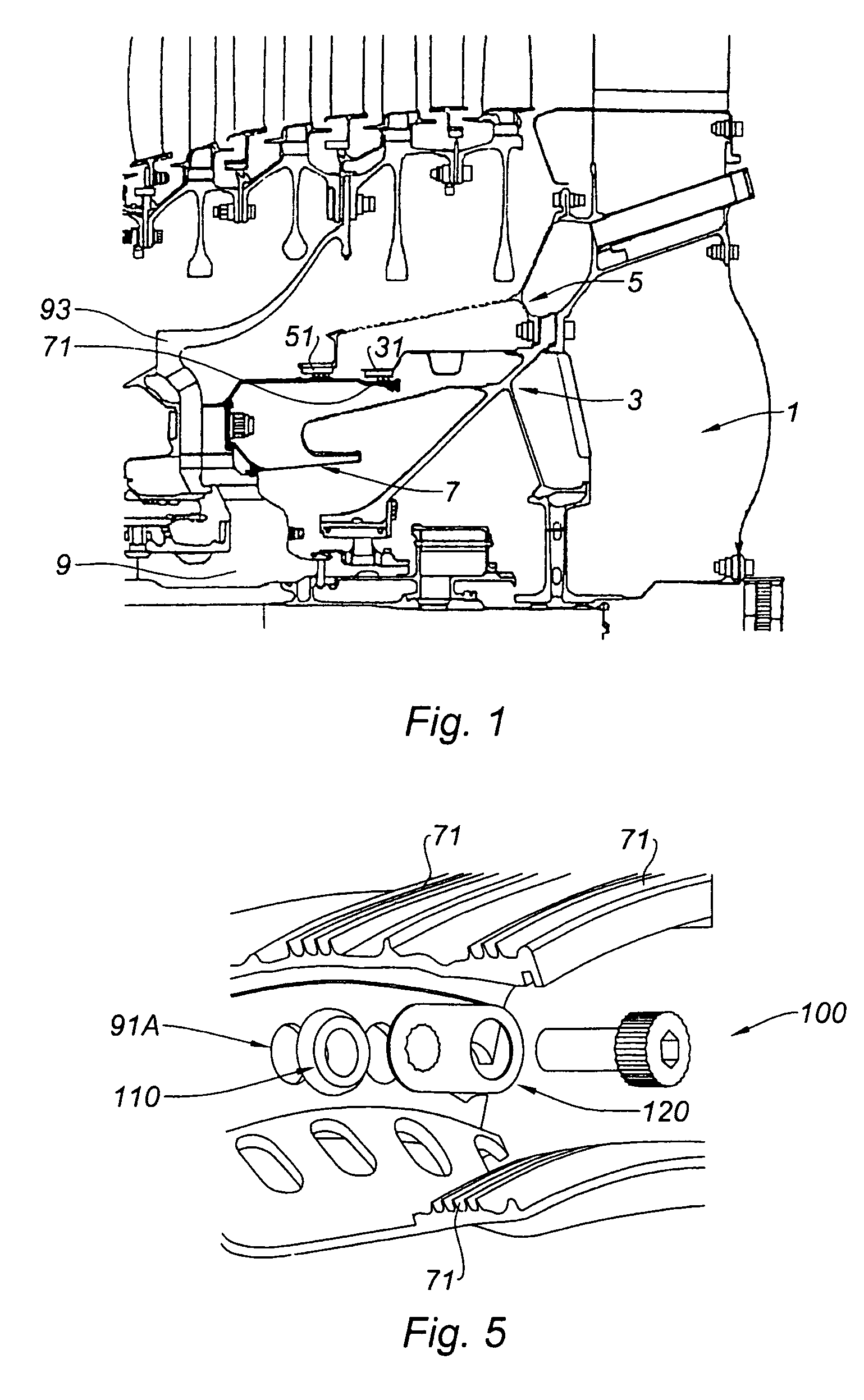
[0022]These tightening screws, that are four in number, one per extraction hole, are screwed into the inserts 91B. A bush 110 takes up the play between the screw 100 and the edge of the cor...


PUM

PropertyMeasurementUnit
pressureaaaaaaaaaa
radial distanceaaaaaaaaaa
diametersaaaaaaaaaa

Abstract

A method of attaching a labyrinth seal support to a turbine engine shaft is disclosed. The method includes inserting axial bolts to secure the labyrinth seal support, the shaft and a device for driving the turbine module with the shaft, and screwing tightening screws in extracting holes, for extracting the drive device with respect to the shaft, provided on the shaft to tighten the labyrinth seal support onto the shaft.

Description

BACKGROUND OF THE INVENTION[0001]1. Field on the Invention[0002]The invention relates to the field of turbine engines and gas turbine engines in particular and concerns the assembly of an element forming a support for a labyrinth seal on a rotor of the engine.[0003]2. Description of Related Art P A gas turbine engine comprises at least one rotating shaft mounted inside a fixed structure forming the stator, and in which it is supported by bearings. The bearings are enclosed in housings receiving, in particular, lubricating oil. Seals, generally labyrinth seals, are positioned between the support for a bearing and the rotor, so as to prevent oil which serves to lubricate the bearing from escaping out of the bearing zone and contaminating the engine.[0004]A labyrinth seal comprises a moveable part integral with the rotor and a fixed part integral with the stator. The moveable part consists of a revolving part at the surface of which a plurality of radial blades or seal teeth are provid...

Claims


Application Information

Patent Timeline
Patent Type & Authority Patents(United States)
IPC IPC(8): B21K25/00B23P15/04
CPCF01D5/066F02C7/20F02C7/28F05B2260/301Y10T29/49329F05D2230/70Y10T29/49327Y10T29/49316Y10T29/49318F05D2260/30
Inventor DEJAUNE, CLAUDE GERARD RENEGROS, VALERIE
Owner SN DETUDE & DE CONSTR DE MOTEURS DAVIATION S N E C M A
Why Eureka
Try Eureka