Method for virtually modeling a dental arch

a virtual model and dental arch technology, applied in dentistry, dental prosthetics, medical science, etc., can solve the problems of increasing the labor and unpleasantness of the entire procedure, the patient's approach is not very expedient, and the patient's experience is not very pleasant, so as to achieve the effect of less onerousness for the patient, high dimensional accuracy of the virtual model, and high level of detail

Active Publication Date: 2020-08-27
GERSTENKAMP GUSTAV
View PDF0 Cites 0 Cited by
  • Summary
  • Abstract
  • Description
  • Claims
  • Application Information

AI Technical Summary

Benefits of technology

[0015]The images of the partial impression on the impression plate, for their part, form the interface to the images of the actual dental arch, since they represent the exact negative of certain partial regions of the dental arch. In the images of the dental arch, it is possible to identify those regions which are represented by the partial impression in the reference body and their distances from one another can be determined exactly due to the pattern. These exactly determined distances can then be transferred to the virtual dental arch model, such that registration errors that occurred during its computation can be corrected. At the same time, it is not necessary to produce a complete impression of the dental arch, which is unpleasant for the patient and which requires significant technical expertise. Rather, it is sufficient to make one flat partial impression, e.g. with a scannable bite registration material, which is less onerous for the patient.
[0016]The method according to the invention thus delivers a particularly high dimensional accuracy of the virtual model, in particular a correction (or—included by this term—an avoidance) of registration errors and minimizes at the same time the burden for the patient.
[0020]to create the (final) dental arch model, the dimensions of the preliminary dental arch model are corrected based on dimensions, realized in the reference model, of those structural features which are present both in the preliminary dental arch model as well as in the reference model.
[0021]In other words, independently of one another, a preliminary dental arch model (namely on the basis of the intraorally captured dental arch images) as well as a reference model (on the basis of the extraorally captured reference body images) are computed first. The preliminary dental arch model contains all structural details of the dental arch, but also the registration errors explained above. Conversely, the reference model is correct with regard to dimensions; however, it only contains few structural details. In a correction step, both models are virtually “superimposed over one another,” w

Problems solved by technology

This approach is generally referred to as “stitching.” Minor errors, influenced by the finite pixel size of the camera used, among other factors, necessarily result during every instance of “stitching.” These are known as “registration errors.” When modeling large regions in particular, such as a complete dental arch, these registration errors can add up to orders of magnitude of multiple hundreds of microns, such that certain dimensions of the virtual model, such as the distance between two opposing molars, deviate from the true dimensions to the extent specified.
With regard to this system, installing said reference body intraorally is disadvantageous, as this makes the entire procedure more laborious and unpleasant for the patient.
This approach appears not to be very expedient, however, at least in the cases in which a physical model is dispensed with or a virtual model is intended to serve as the basis for a physical model.
This leads to further inaccuracies, especially where an installed reference body obscures structural details of the dental arch and/or of the phy

Method used


Image

  • Method for virtually modeling a dental arch
  • Method for virtually modeling a dental arch
  • Method for virtually modeling a dental arch

Examples


Embodiment Construction

[0042]Identical reference symbols in the figures indicate identical or analogous elements.

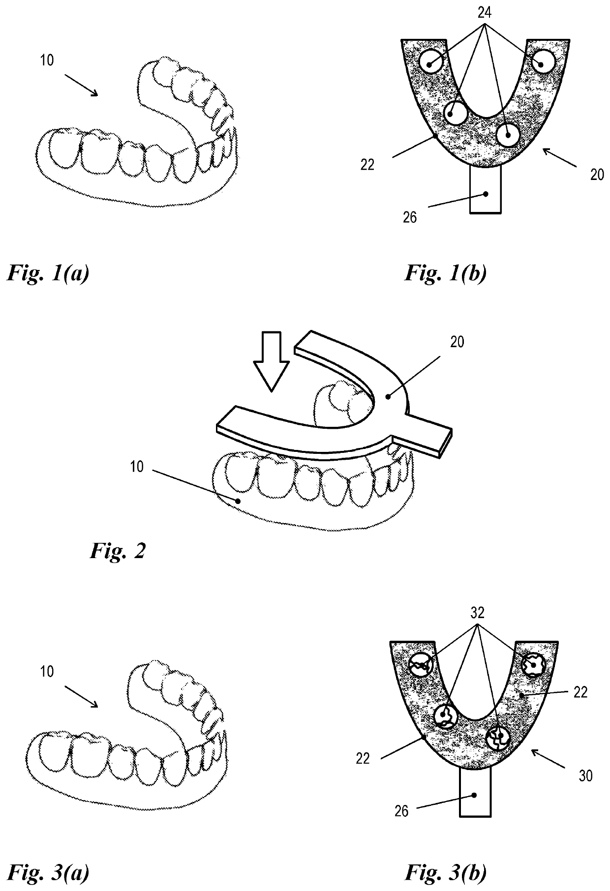
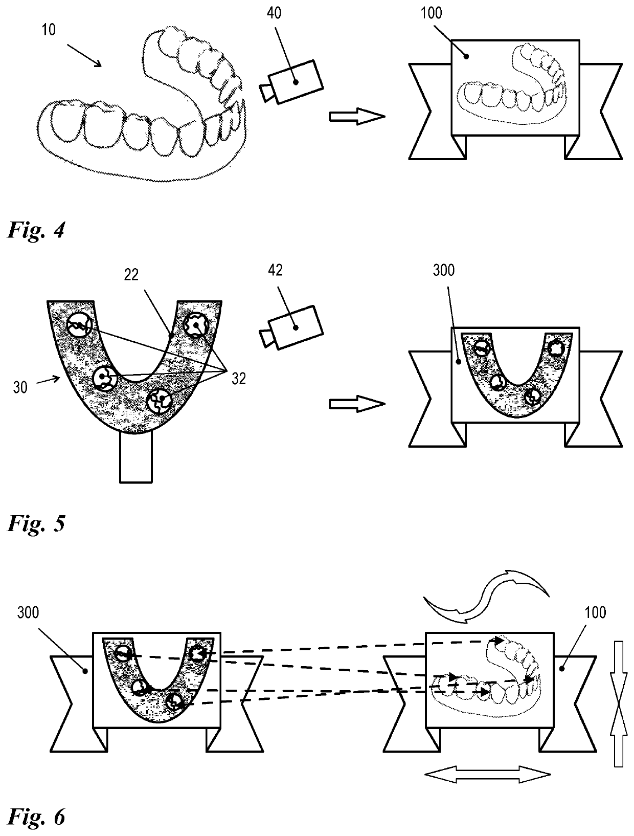
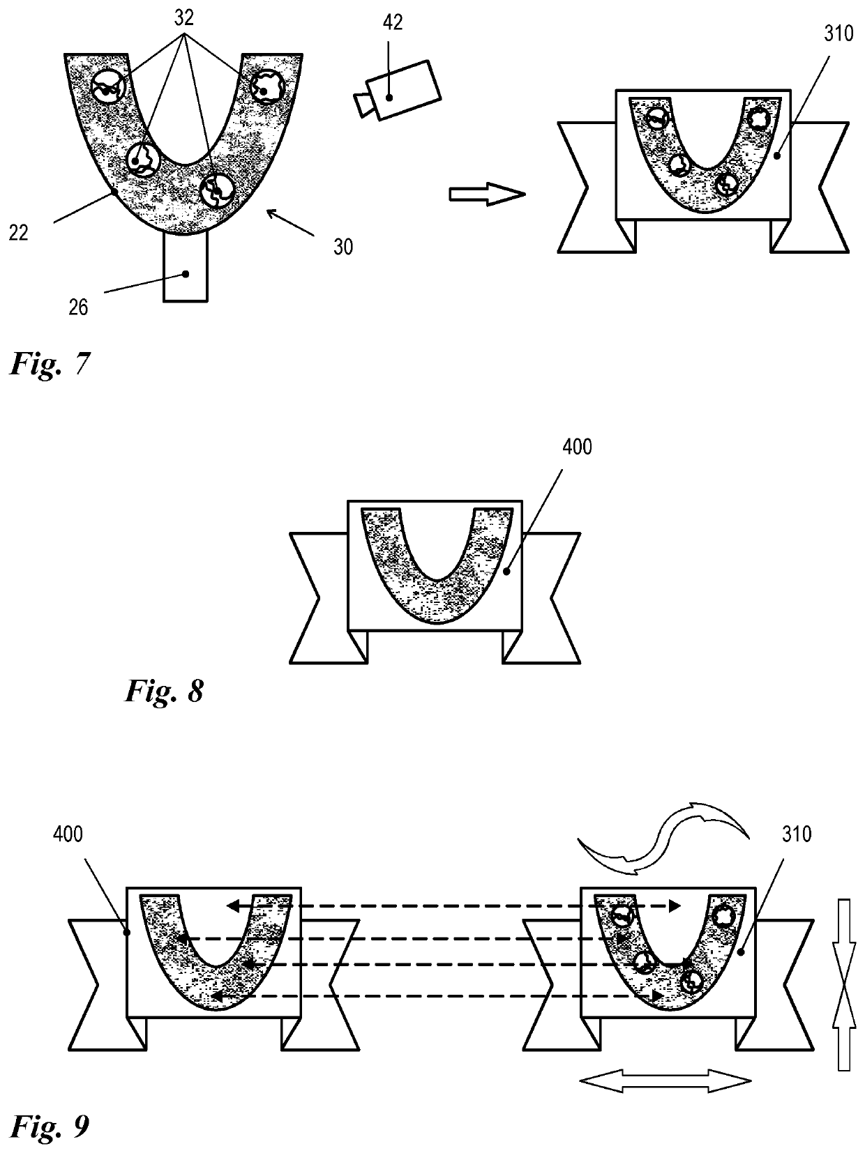
[0043]FIGS. 1 to 6 show an advantageous embodiment of a method according to the invention for virtual modeling of a dental arch 10. In Sub-FIG. 1a, the dental arch 10 is shown in isolated fashion. This serves only the purposes of clarity of the drawings, however. The method according to the invention relates in particular to the modeling of a dental arch 10 in situ. Sub-FIG. 1b shows an impression body 20, such as is preferably used in the context of the method according to the invention. The impression body is composed of an impression plate 22, that bears a non-periodic relief-type pattern, which is preferably composed of statistically distributed pattern elements, especially preferably of ball segments with different radii and / or different heights. On the impression plate 22, multiple—four in Sub-FIG. 1b—portions 24 of deformable impression material are positioned in isolated fashion from on...


PUM


Abstract

The invention relates to a method for virtually modeling a dental arch (10), wherein a plurality of overlapping images of the dental arch (10) and of a reference body (30) is captured from different angles of view and a virtual, three-dimensional dental arch model is computed from the captured images.
The invention is characterized in that a partial impression (32) of the dental arch (10) on an impression plate (22) of known dimensions is used as the reference body (30), which impression plate is provided with a pattern.

Description

BACKGROUNDField of the Invention[0001]The invention relates to a method for virtually modeling a dental arch, wherein a plurality of overlapping images of the dental arch and of a reference body is captured from different angles of view and a virtual, three-dimensional dental arch model is computed from the captured images.Related Art[0002]WO 03 / 100 729 A1 discloses a known method for virtually modeling a dental arch.[0003]In dentistry, especially jaw surgery and dental prosthetics, exact dental arch models of patient dentitions are often required. In the present context, the term ‘dental arch’ should be understood broadly and comprises not only a complete arcus dentalis but also partial regions thereof. The term applies equally to tooth arrangement as such, as well as to the tooth-bearing structures (whether toothed or untoothed).[0004]Physical models of dental arches often form the basis for dental lab adjustment work, which can be performed extraorally in this manner. Traditional...

Claims


Application Information

Patent Timeline
IPC IPC(8): A61C9/00
CPCA61C9/0006A61C9/0053A61C19/05A61C9/00A61C13/00A61C19/04
Inventor GERSTENKAMP, GUSTAV
Owner GERSTENKAMP GUSTAV
Why Eureka
Try Eureka