
Provisional orthopedic implant and recutting instrument guide

a technology of instrument guide and orthopaedic implant, which is applied in the field of orthopaedic prosthesis to achieve the effect of simplifying the alignment of the instrument guide on the bon

Inactive Publication Date: 2011-06-21
ZIMMER TECH INC
View PDF18 Cites 20 Cited by
  • Summary
  • Abstract
  • Description
  • Claims
  • Application Information

AI Technical Summary

Benefits of technology

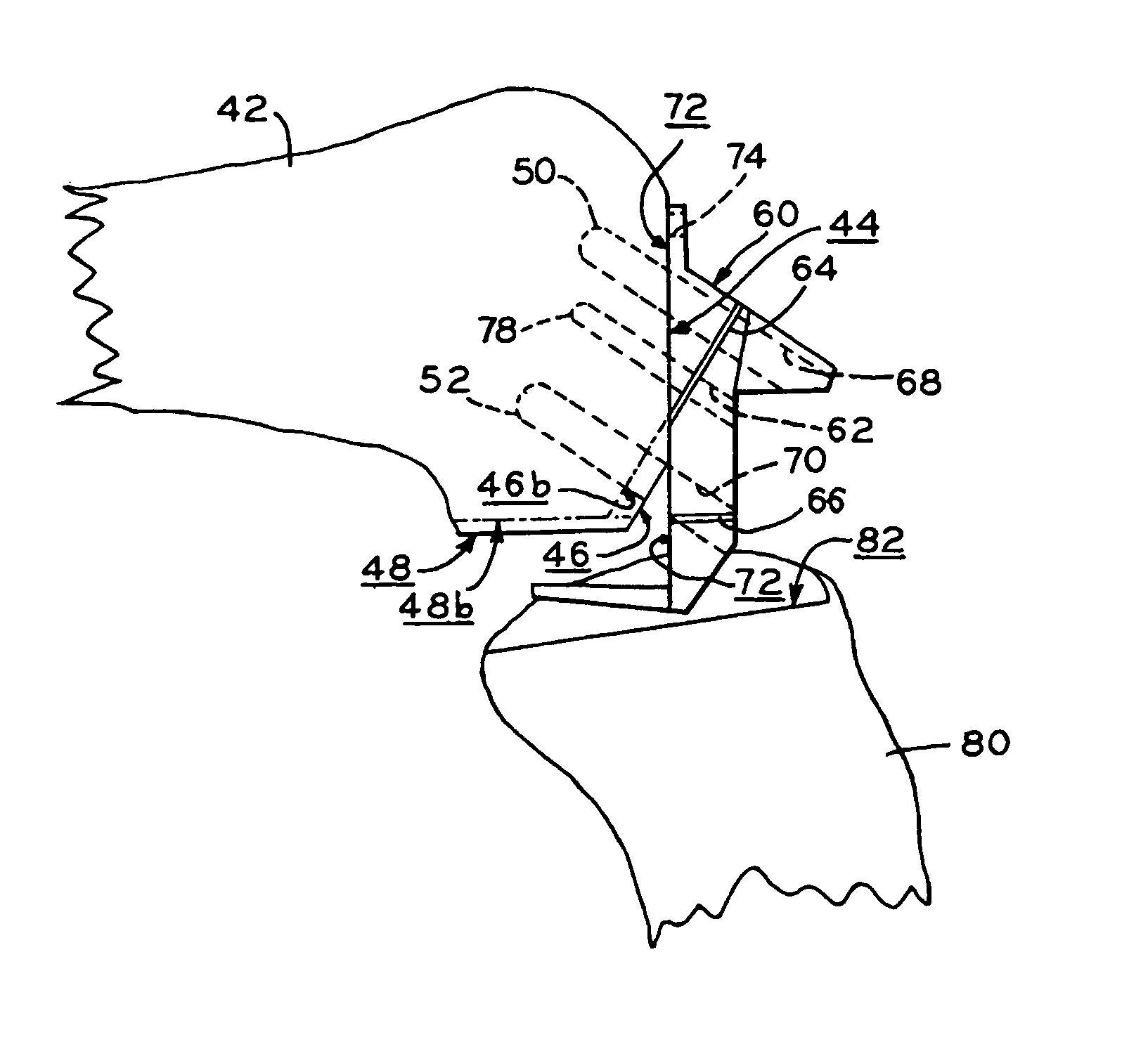
[0020]An advantage of the present invention is that it provides a provisional component that may be used to assess the fit of a orthopedic prosthetic component and, if the assessment indicates that a differently sized prosthetic component should be selected, the provisional component includes referencing elements which may be used to mark the bone to properly align an instrument guide on the bone to recut or otherwise prepare the bone to receive the newly selected prosthetic component. This provides a relatively convenient procedure for revising the bone surface to receive the newly selected prosthetic component which simplifies the alignment of the instrument guide on the bone.
is that it provides a provisional component that may be used to assess the fit of a orthopedic prosthetic component and, if the assessment indicates that a differently sized prosthetic component should be selected, the provisional component includes referencing elements which may be used to mark the bone to properly align an instrument guide on the bone to recut or otherwise prepare the bone to receive the newly selected prosthetic component. This provides a relatively convenient procedure for revising the bone surface to receive the newly selected prosthetic component which simplifies the alignment of the instrument guide on the bone.

Problems solved by technology

A trial reduction of the knee joint with the provisional components in place may indicate that the preliminary size determination was incorrect, that the gap between the femur and tibia is insufficient, or some other undesirable characteristic which requires the selection of a different sized tibial or femoral component thereby necessitating the further resection of either the tibia or femur.

Method used


Image

  • Provisional orthopedic implant and recutting instrument guide
  • Provisional orthopedic implant and recutting instrument guide
  • Provisional orthopedic implant and recutting instrument guide

Examples


Embodiment Construction

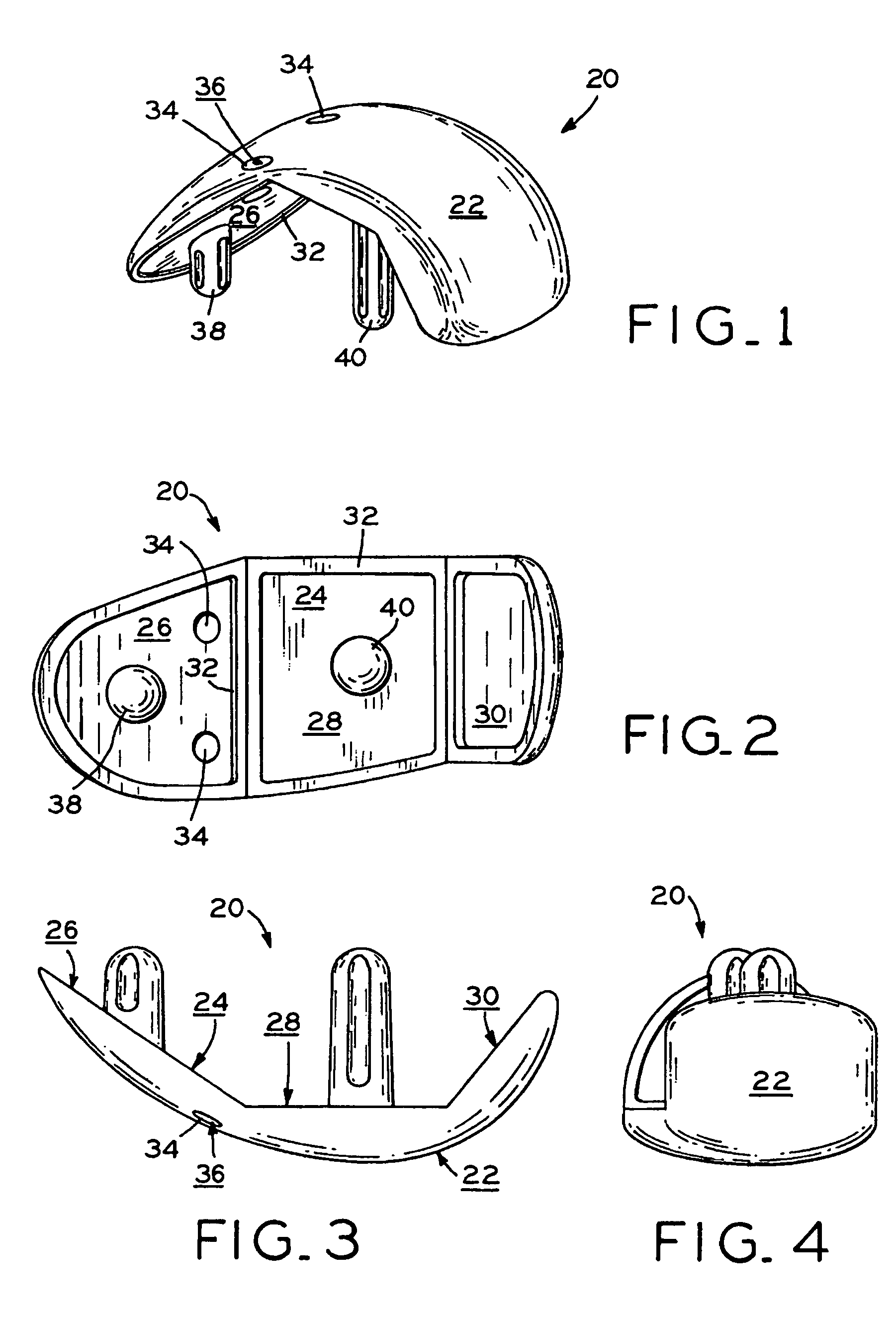
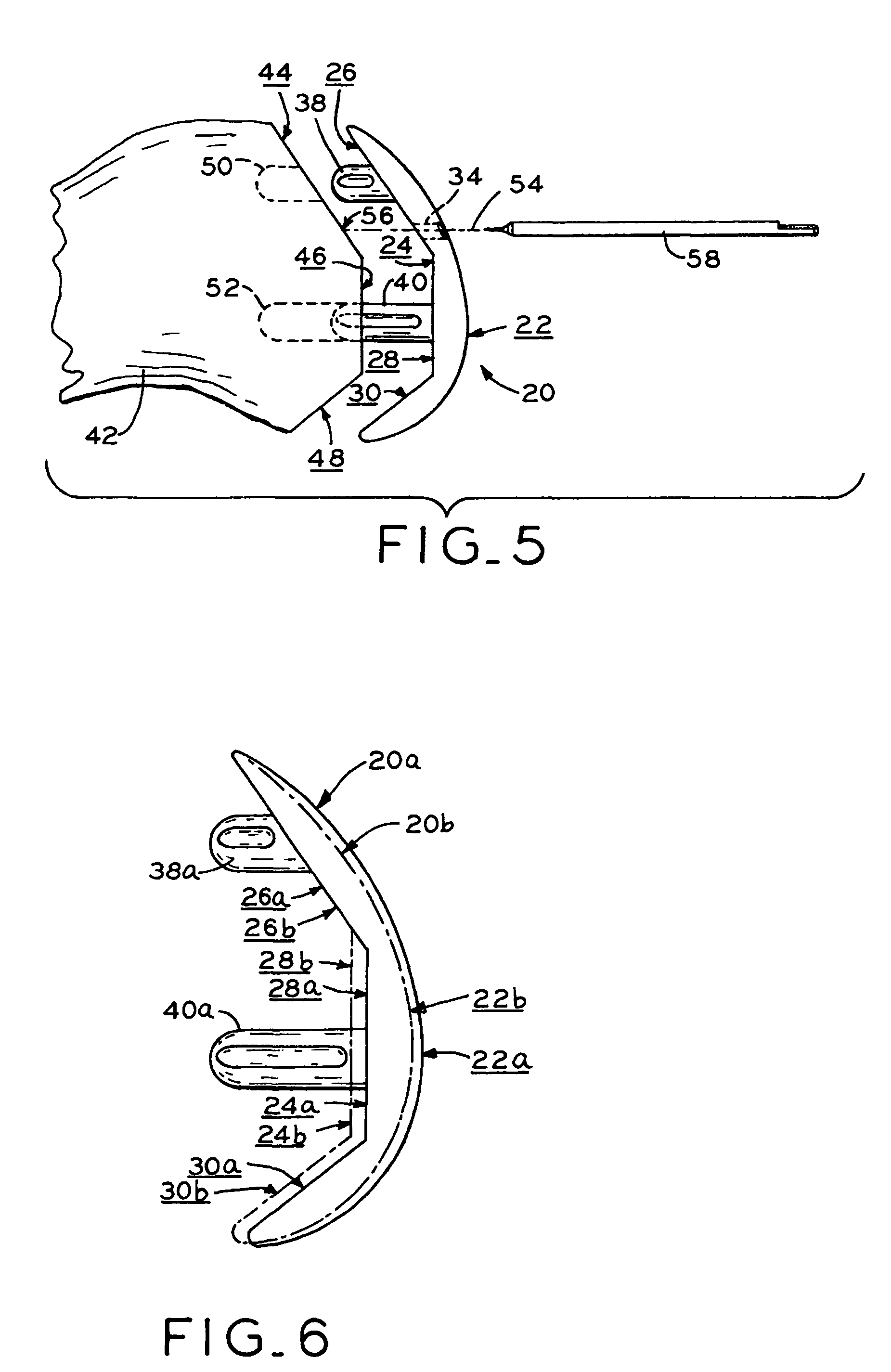
[0031]A provisional component 20 in accordance with the present invention is shown in FIG. 1. Provisional component 20 has an outwardly facing surface 22 which defines a single condylar-shaped projection and an oppositely disposed inward facing surface 24. Inward facing surface 24 has three substantially planar sections 26, 28, 30. A small ridge 32 defines the perimeter of the three intersecting planar sections 26, 28 and 30. Cylindrical openings extending from outer surface 22 to inner surface 24 define passages 34. The interior surface of passages 34 defines a registry surface 36 as discussed in greater detail below. Mounting posts 38, 40 are provided for removably mounting provisional component 20 to a femur 42.

[0032]The mounting of provisional component 20 to a femur 42 is best seen in FIG. 5. In FIG. 5, femur 42 has been resected leaving a distal cut 44, a chamfer cut 46 and a posterior cut 48. Resected surfaces 44, 46, 48 define three intersecting planes having a configuration...


PUM


Abstract

A provisional component for use with differently sized first and second prosthetic orthopedic components. The provisional component has a configuration which is substantially similar to the first prosthetic component and has a predefined correspondence to the second prosthetic component. The provisional component is mounted on a bone to assess the fit of the first prosthetic component. The provisional component includes a referencing element for defining a reference point on the bone if the fit of the provisional component indicates that the second prosthetic component should be used. An instrument guide is aligned with the reference point and used to properly position a surgical instrument to prepare the bone to receive the second prosthetic component. The provisional and prosthetic components may all be femoral components which have an articulating surface defining a single condylar-shaped projection.

Description

CROSS REFERENCE TO RELATED APPLICATIONS[0001]This is a Divisional of U.S. patent application Ser. No. 10 / 357,721, filed Feb. 4, 2003, now U.S. Pat. No. 7,172,597, the disclosure of which is hereby expressly incorporated herein by reference.BACKGROUND[0002]1. Field of the Invention[0003]The present invention relates to orthopedic prostheses and, more particularly, to a provisional orthopedic prosthetic component that can be used to facilitate the selection of one of at least two differently configured permanent prosthetic components and the proper positioning of an instrument guide for preparing the bone that will receive the permanent prosthetic component.[0004]2. Description of the Related Art[0005]The use of orthopedic implants to form artificial joints such as prosthetic knees is well known in the art. During a conventional surgical procedure to implant a prosthetic knee joint, a provisional femoral component and a provisional tibial component are placed on the distal femur and p...

Claims


Application Information

Patent Timeline
Patent Type & Authority Patents(United States)
IPC IPC(8): A61B17/56A61B17/15A61F2/00A61F2/30A61F2/38A61F2/46
CPCA61B17/155A61F2/38A61F2/4684A61F2/3859A61F2250/0037A61F2002/30616A61F2002/30827A61F2002/30892A61F2002/3895A61F2002/30326
Inventor SANFORD, ADAM H.
Owner ZIMMER TECH INC
Learn More