Device for generating stiffness and joint of robot manipulator comprising the same

a robot manipulator and joint technology, applied in the field of generating stiffness, can solve the problems of inability to rapidly vary the stiffness of the robot manipulator, inability to control the stiffness according to its operation, and no measure or remedy in case of electrical breakdown, so as to achieve simple constitution, generation and variation of the stiffness, the effect of simple constitution

Active Publication Date: 2011-06-21
KOREA INST OF SCI & TECH
View PDF12 Cites 38 Cited by
  • Summary
  • Abstract
  • Description
  • Claims
  • Application Information

AI Technical Summary

Benefits of technology

[0019]The stiffness generating device of the present invention can generate stiffness with a simpler constitution than that of the prior art by generating stiffness through using magnetic force of electromagnets or permanent magnets.
[0020]In case of the stiffness generating device using the electromagnets, since stiffness is generated and the generated stiffness is varied by application of current without additional control, the generation and variation of stiffness are accomplished with a simpler constitution compared to complicated control of the prior art.
[0021]In case of the stiffness generating device using the permanent magnets, the generation and variation of stiffness are accomplished with a simple constitution and a rapid control.

Problems solved by technology

However, it operates only with determined spring constant and controlling its stiffness according to its operation is impossible.
Thus, there is a problem in that stiffness cannot be rapidly varied.
In said light weight robot, however, although the spring effect is shown without any separate mechanism, there is no measure or remedy in case of an electrical breakdown.
Further, there is a problem in that efficiency and performance are low since position control and force control are carried out by a single controller.

Method used


Image

  • Device for generating stiffness and joint of robot manipulator comprising the same
  • Device for generating stiffness and joint of robot manipulator comprising the same
  • Device for generating stiffness and joint of robot manipulator comprising the same

Examples


first embodiment

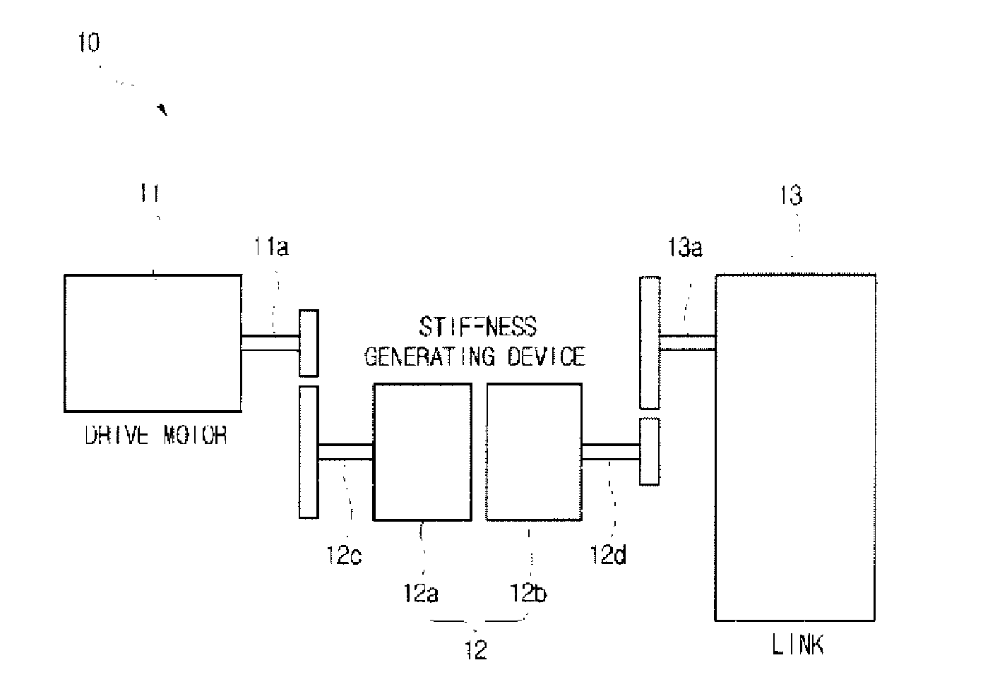
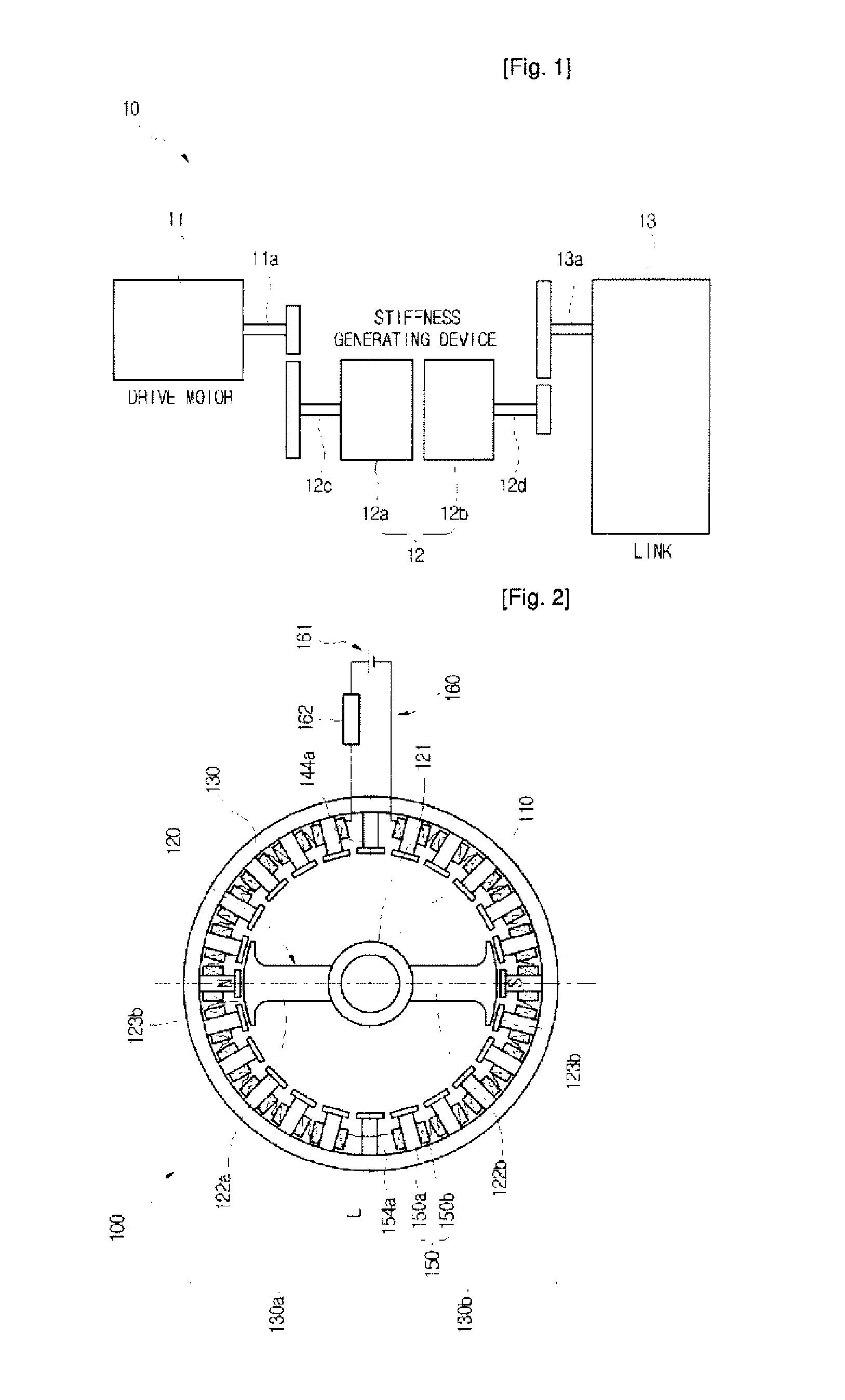
[0037]FIG. 2 is a sectional view showing a stiffness generating device according to the present invention.

[0038]Referring to FIG. 2, a stiffness generating device 100 of this embodiment comprises the following: a rotating shaft 110 connected to a driven member; a rotor 120 fixedly coupled to the rotating shaft 110 to be rotated together with the rotating shaft 110; a stator 130 disposed so as to surround the rotor 120 and being connected to a drive motor for driving the driven member to be rotated by a rotation of the drive motor; and a plurality of electromagnets 140, 150 disposed in a circumferential direction of the stator 130.

[0039]The rotating shaft 110 is connected to the driven member at its one end portion to thereby serve to transmit the rotation of the drive motor to the driven member. The driven member comprises a link constituting a robot manipulator.

[0040]The rotor 120 is an element moving relatively with respect to the stator 130. The rotor includes: a hub 121 fixed to...

third embodiment

[0066]FIG. 6 is a sectional view showing a stiffness generating device according to the present invention.

[0067]The stiffness generating device 300 of this embodiment has the same constitution as the stiffness generating device 100 of the first embodiment except that the rotor includes permanent magnets and a cross-sectional shape of the stator is elliptical. Like reference numerals refer to like elements in comparison with the stiffness generating device 100 of the first embodiment and descriptions relating thereto are omitted herein.

[0068]The rotor 120 has permanent magnets 324 in each arm 122a, 122b. The permanent magnets 324 are disposed in the arms 122a, 122b so as to correspond to the magnetic poles formed at the ends of the cores facing toward the rotating shaft 110. The permanent magnets 324 may be disposed in the middle of the arms 122a, 122b or may be disposed in the reaction portions 123a, 123b.

[0069]A stator 330 is configured as an elliptically cross-sectioned ring or c...

fourth embodiment

[0071]FIG. 7 is a sectional view showing a stiffness generating device according to the present invention.

[0072]The stiffness generating device 400 of this embodiment has a similar constitution to the stiffness generating device 100 of the first embodiment except that the configuration of the rotor is modified so as to enhance the restoring force of the rotor and the winding arrangement of the coils are modified accordingly. Like reference numerals refer to like elements in comparison with the stiffness generating device 100 of the first embodiment and descriptions relating thereto are omitted herein.

[0073]A rotor 420 fixed to the rotating shaft to be rotated together therewith includes the following: a hub 421 fixed to the rotating shaft 110; four arms 422a to 422d extending from the hub 421 at equal intervals and radially outwardly; reaction portions 423a to 423d formed at each distal end of each atm 422a to 422d; and rotor coils 424 wound around respective arms 422a to 422d.

[007...


PUM


Abstract

A device for generating and varying stiffness, which may be applied to a joint of a robot manipulator, the stiffness generating device having a rotating shaft connected to a driven member; a rotor fixed to the rotating shaft and having arms comprising a magnetic element; a stator disposed to surround the rotor outside the arms and being connected to a drive motor; electromagnets fixed to an inner periphery of the stator and being opposed to each other about the rotating shaft, each having a core and a coil wound around the core; and means for applying current to the coils. One half of the electromagnets has N-poles at their inward ends and the other half of the electromagnets has S-poles at their inward ends. Current regulating means regulates the current being applied to the coils.

Description

TECHNICAL FIELD[0001]The present invention generally relates to a device for generating stiffness, and more particularly to a device for generating variable stiffness by using a magnetic force, which can be applied to a joint of a robot manipulator.BACKGROUND ART[0002]As examples of prior art for providing stiffness, which are applied to joints of a robot manipulator, there is one approach that uses a mechanical spring. Further, there is another approach that detects forces exerted on a manipulator and controls a drive motor of a joint accordingly to accomplish the effect of virtual spring without any additional mechanism.[0003]A document entitled “The second IARP-IEEE / RAS Joint Workshop on Technical Challenge for Dependable Robots in Human Environment” (KOREA INSTITUTE OF SCIENCE AND TECHNOLOGY, pp. 88-95, 2002) discloses “Safe arm design for service robot” (Kim). The arm design disclosed in such a document enhances safety of a manipulator by additionally mounting a mechanical spri...

Claims


Application Information

Patent Timeline
Patent Type & Authority Patents(United States)
IPC IPC(8): H02K49/00
CPCB25J19/0004Y10T74/20329B25J17/00B25J19/0045B25J13/088
Inventor KANG, SUNG CHULKIM, MUNSANGKIM, SEUNG JONGYUN, SEUNG KOOKYOO, JEONGHOON
Owner KOREA INST OF SCI & TECH
Why Eureka
Try Eureka