
Steering shaft support structure and vehicle

a technology of supporting structure and steering shaft, applied in the direction of electrical steering, transportation and packaging, bicycles, etc., to achieve the effect of increasing displacemen

Inactive Publication Date: 2011-06-28
HONDA MOTOR CO LTD
View PDF14 Cites 1 Cited by
  • Summary
  • Abstract
  • Description
  • Claims
  • Application Information

AI Technical Summary

Benefits of technology

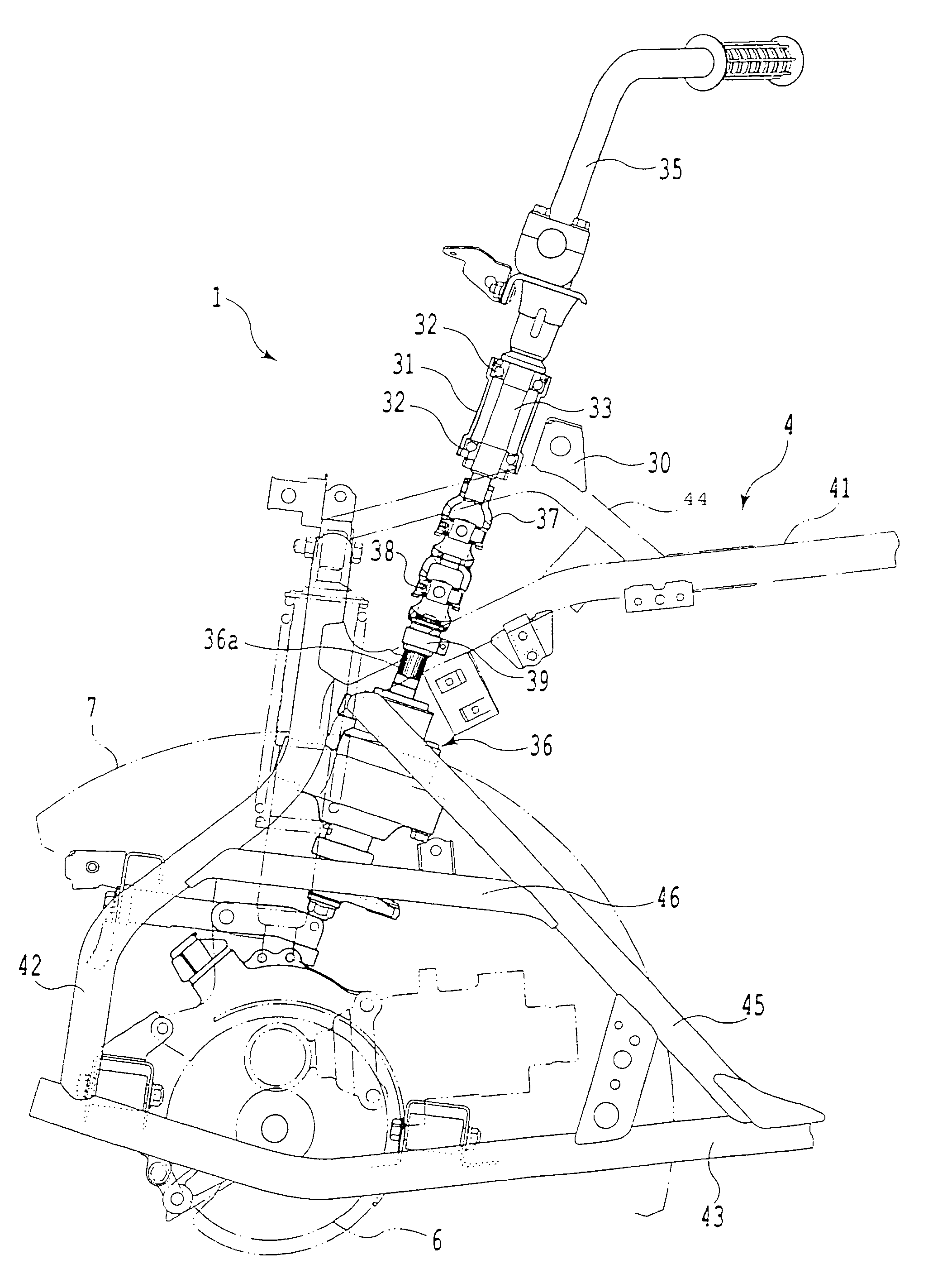
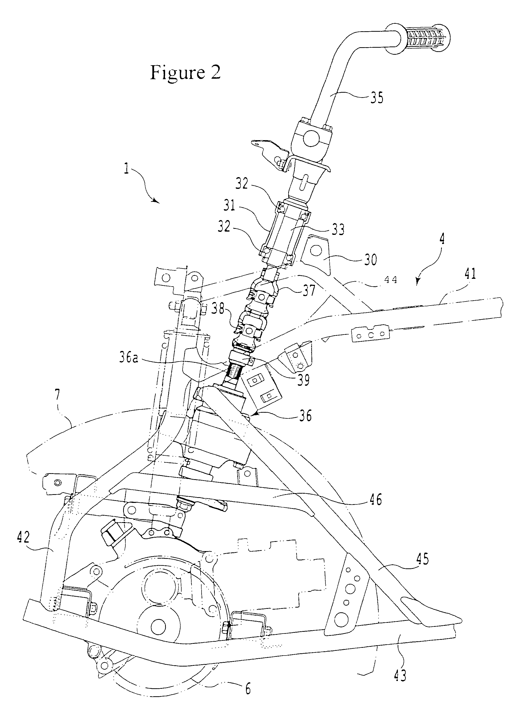
[0013]According to the present invention, since the plurality of sets of adjustable joints are interposed between the steering shaft and the EPS unit, if a load is applied to the handlebars, the adjustable joint associated with the steering shaft follows the inclination of the steering shaft, thereby absorbing the inclination. Therefore, even if a load is applied to the handlebars, the connection point (swing point) of the adjustable joint associated with the EPS unit does not shift. This can reduce both forces of push and pull applied to the EPS unit.
[0014]In addition, since the axes of the plurality of sets of adjustable joints are offset from each other, increased displacement can be ensured when the adjustable joint are pulled by the inclination of the steering shaft.
[0015]Further, since the steering shaft is rotatably supported at a plurality of points by the head pipe, the inclination of the steering shaft can be suppressed and also the shaft center of the steering shaft can be positioned high-precisely
[0016]Still further, since the adjustable joints are disposed in a space enclosed by the body frame, they are unlikely to come into contact with other components, thereby exhibiting their own functions sufficiently.

Problems solved by technology

However, since this configuration has only one adjustable joint, if a load is applied to the handlebars due to some causes, the steering shaft is inclined with respect to a point of connection with the body frame.

Method used


Image

  • Steering shaft support structure and vehicle
  • Steering shaft support structure and vehicle
  • Steering shaft support structure and vehicle

Examples


Embodiment Construction

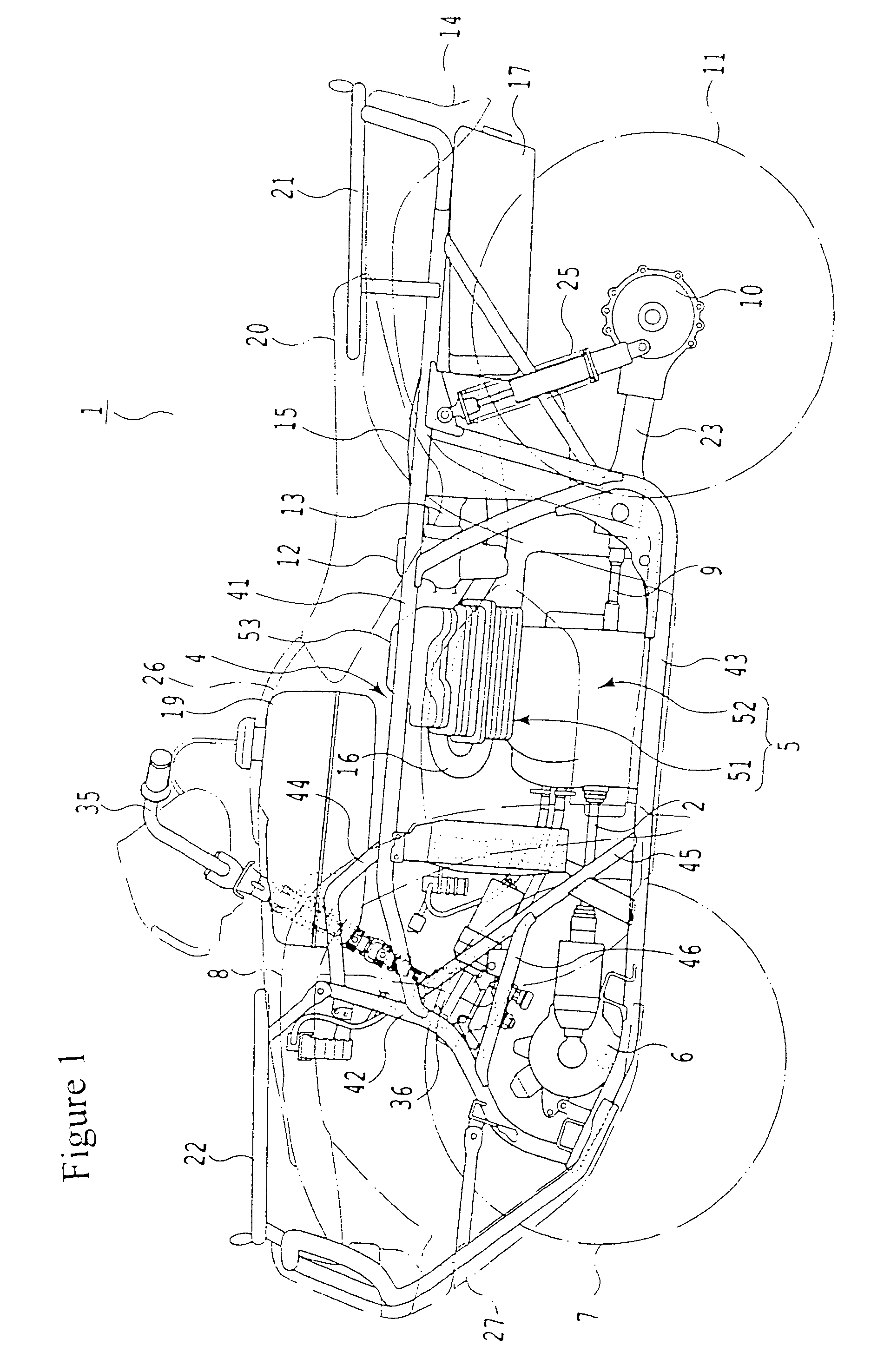
[0023]With reference to FIG. 1, an all terrain vehicle (vehicle) 1 includes a body frame 4. The body frame 4 includes a pair of left and right upper main frames 41 extending in a back-and-forth direction, a front frame 42, a pair of left and right lower main frames 43, a pair of left and right front upper frames 44, a pair of left and right tilt frames 45, and a pair of left and right sub tilt frames 46. The front frame 42 has an inverse-U shape as viewed from the front and is joined to the front ends of the upper main frames 41. The lower main frames 43 are each spanned between and joined to the lower end of the front frame 42 and an intermediate portion of the upper main frame 41. The front upper frames 44 are each doglegged and spanned between and joined to the upper end of the front frame 42 and a portion, slightly rearward of the front end, of the upper main frame 41. The tilt frames 45 each extend from the front end of the upper main frame 41 obliquely downwardly and joined to...


PUM


Abstract

A steering shaft support structure for an all terrain vehicle in which both forces of push and pull applied to an EPS unit are reduced when a load is applied to handlebars. The structure includes a steering shaft rotatably supported by a body frame and handlebars attached to the steering shaft. The EPS unit is also supported by the body frame. Two sets of adjustable joints are interposed between the steering shaft and the EPS unit in such a manner that their axes are shiftable. With this, if a load is applied to the handlebars, the adjustable joint associated with the steering shaft follows the inclination of the steering shaft, so that the connection point (swing point) of the adjustable joint associated with the EPS unit does not shift. This reduces both forces of push and pull applied to the EPS unit.

Description

CROSS-REFERENCE TO RELATED APPLICATION[0001]The present application claims priority under 35 U.S.C. §119 to Japanese Patent Application No. 2005-315631, filed Oct. 31, 2006, the entire contents of which are hereby incorporated by reference.BACKGROUND OF THE INVENTION[0002]1. Field of the Invention[0003]The present invention relates to a steering shaft support structure suitably applicable to vehicles such as all terrain vehicles (ATV).[0004]2. Description of Background Art[0005]The conventional vehicles of this type are configured such that a steering shaft is rotatably supported by an upper portion of a body frame via a bearing and a bushing and an EPS (Electric Power Steering) unit is supported by a lower portion of the body frame. The lower end of the steering shaft is connected to the input shaft of the EPS unit via an adjustable joint (see e.g. Japanese Patent Laid-open No. 2004-231011 (paragraph [0031], FIG. 4).[0006]However, since this configuration has only one adjustable jo...

Claims


Application Information

Patent Timeline
Patent Type & Authority Patents(United States)
IPC IPC(8): B62D5/02
CPCB62D1/18B62K5/08B62K5/01
Inventor OKADA, MEGUMUYAGI, KEITAMORI, YOTAROWAKABAYASHI, TAKESHIKAITA, KIHOKO
Owner HONDA MOTOR CO LTD
Learn More