
Mechanical installation assistive device with power-assisted lifting function

A mechanical and auxiliary technology, used in manufacturing tools, workbenches, workshop equipment, etc., can solve the problems of difficult installation of fuel tanks and high labor intensity of installation, and achieve the goal of reducing labor intensity, reducing the number of workers, and reducing labor intensity. Effect

Inactive Publication Date: 2021-02-26
DONGFENG AUTOMOBILE COMPANY
View PDF10 Cites 0 Cited by
  • Summary
  • Abstract
  • Description
  • Claims
  • Application Information

AI Technical Summary

Problems solved by technology

[0007] The purpose of the present invention is to overcome the problems of difficult installation of the fuel tank and high installation labor intensity in the prior art, and to provide a mechanical lifting and lowering installation aid that is easy to install, reduces installation labor intensity, and reduces labor

Method used


Image

  • Mechanical installation assistive device with power-assisted lifting function
  • Mechanical installation assistive device with power-assisted lifting function
  • Mechanical installation assistive device with power-assisted lifting function

Examples


Embodiment 1

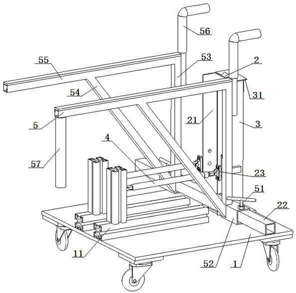
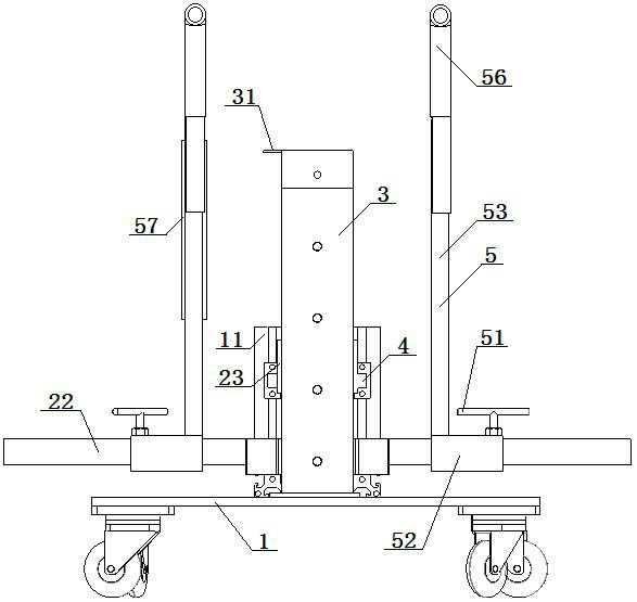
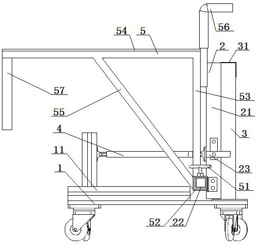
[0046]A mechanical lifting installation aid with power assistance, the installation aid includes: a flat trolley 1 and a lifting bracket 2, the lifting bracket 2 is fixed on the flat trolley 1 through a fixing seat 3, the lifting bracket 2 and the fixed The seat 3 is slidingly fitted; the lifting support 2 is connected with the flat trolley 1 through the gas spring 4; the lifting support 2 includes a lifting slide rail frame 21 and a lower fixed beam 22, and the lower end of the lifting slide rail frame 21 is fixed to the lower The crossbeam 22 is vertically connected, the bottom of the lifting slide rail frame 21 is space-limitingly matched with the top surface of the flat trolley 1, the back of the lifting slide rail frame 21 is slidingly fitted with the fixing seat 3, and the middle and lower part of the lifting slide rail frame 21 passes through The gas spring 4 is connected with the flat trolley 1; an adjustable width tripod 5 is respectively set on both sides of the lower...

Embodiment 2

[0048] Embodiment 2 is basically the same as Embodiment 1, and its difference is:

[0049] Both sides of described lifting slide rail frame 21 are respectively fixedly connected with a spring fixing seat 23, and described flat trolley 1 top is provided with two spring fixing brackets 11, and described two spring fixing brackets 11 are arranged in parallel, and described two The spring fixing bracket 11 is relatively arranged with the fixing seat 3, and each of the two spring fixing brackets 11 is connected with the spring fixing seat 23 by a gas spring 4, and one end of the gas spring 4 is rotatably matched with the spring fixing bracket 11, so that The other end of the gas spring 4 is rotatably engaged with the spring holder 23, and the two gas springs 4 are arranged in parallel.

Embodiment 3

[0051] Embodiment 3 is basically the same as Embodiment 2, and its difference is:

[0052] The back of described lifting slide rail frame 21 is provided with the slide rail that cross-section is isosceles trapezoid, and described slide rail is slidably matched with the chute on the fixed seat 3; The top of described fixed seat 3 is provided with upper limit plate 31, so The upper limit plate 31 and the spring fixing seat 23 limit fit; the top of the vertical rod 53 is fixedly connected with a handle 56; one end of the storage rod 54 is fixedly connected with the handle 56, and the other end of the storage rod 54 is fixedly connected Leading rod 57 is arranged.


PUM


Abstract

A mechanical installation assistive device with a power-assisted lifting function comprises a flat car and a lifting support, wherein the lifting support is fixed to the flat car through a fixing base, and the lifting support is in sliding fit with the fixing base. The lifting support is connected with the flat car through a gas spring. The lifting support comprises a lifting sliding rail frame and a lower fixing cross beam, wherein the lower end of the lifting sliding rail frame is perpendicularly connected with the lower fixing cross beam, the bottom of the lifting sliding rail frame is in limiting fit with the top face of the flat car, and the back of the lifting sliding rail frame is in sliding fit with the fixing base. The middle lower portion of the lifting sliding rail frame is connected with the flat car through a gas spring. The two sides of the lower fixing cross beam are each sleeved with a width-adjustable triangular support, the bottoms of the width-adjustable triangular supports are in sliding fit with the lower fixing cross beam, and the width-adjustable triangular supports are in locking fit with the lower fixing cross beam through locking devices. According to thedesign, the lifting structure can effectively reduce the labor intensity of carrying, the structure adjustment is flexible, and the application range is wide.

Description

technical field [0001] The invention relates to a mechanical lifting and lowering installation aid, which is particularly suitable for reducing installation labor intensity and manpower. Background technique [0002] In order to meet the market demand, there are more and more light truck models, and the types of automobile fuel tanks are also increasing accordingly, and the dimensions and weight of the fuel tank are also increasing; in view of this, the assembly of the fuel tank on the final assembly line is facing greater operational difficulties; the fuel tank assembly process The following issues need to be resolved: [0003] 1. The fuel tank has a heavy weight and large differences in dimensions. During the assembly process, the manual work is labor-intensive and the work efficiency is low. The large-sized fuel tank needs 2 people to cooperate to complete; [0004] 2. The weight of different fuel tanks ranges from 20 to 30KG, with an average of 100 units per day, and th...

Claims


Application Information

Patent Timeline
Patent Type & Authority Applications(China)
IPC IPC(8): B25H1/06B25H1/10B25H1/16B25H5/00
CPCB25H1/06B25H1/10B25H1/16B25H5/00
Inventor 魏明伟韩涛刘芳亮陈红梅来辉煌郑辉
Owner DONGFENG AUTOMOBILE COMPANY
Learn More