
Lighting fixture

a technology of light source and light fixture, which is applied in the direction of fixed installation, lighting and heating apparatus, lighting support devices, etc., can solve the problems of poor solid-state lighting environment inside the conventional can described above, poor light source heat generation, and inability to operate in high temperatures. to achieve the effect of convenient mounting

Active Publication Date: 2011-06-28
IDEAL IND LIGHTING LLC
View PDF68 Cites 85 Cited by
  • Summary
  • Abstract
  • Description
  • Claims
  • Application Information

AI Technical Summary

Benefits of technology

The present invention relates to lighting fixtures that use rails for mounting solid state light emitters. The invention provides devices and methods for mounting lighting fixtures to construction elements using rails. The invention also addresses various considerations that arise when using such fixtures, such as the use of multiple rails and the need for engagement elements to prevent sliding of the rails. The invention also includes a lighting fixture that has a spring clip for securely holding a light engine housing in place. Overall, the invention provides improved methods and devices for mounting lighting fixtures using rails.

Problems solved by technology

As the lamp is mounted in the can, much of the heat generated by the light source is trapped within the can, because the air heated in the can rises and is trapped within the can.
The environment inside a conventional can are described above is not ideal for solid-state lighting.
LEDs, for example, have significant energy and lifetime benefits over incandescent and fluorescent light sources—LEDs, however, do not operate well in high temperatures.
An LED's lifetime is significantly shortened, however, if it operates at elevated temperatures.

Method used


Image

  • Lighting fixture
  • Lighting fixture
  • Lighting fixture

Examples


first embodiment

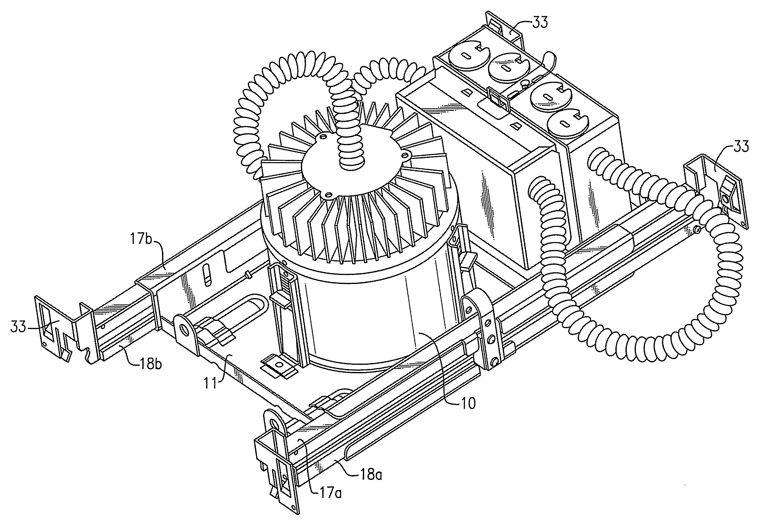
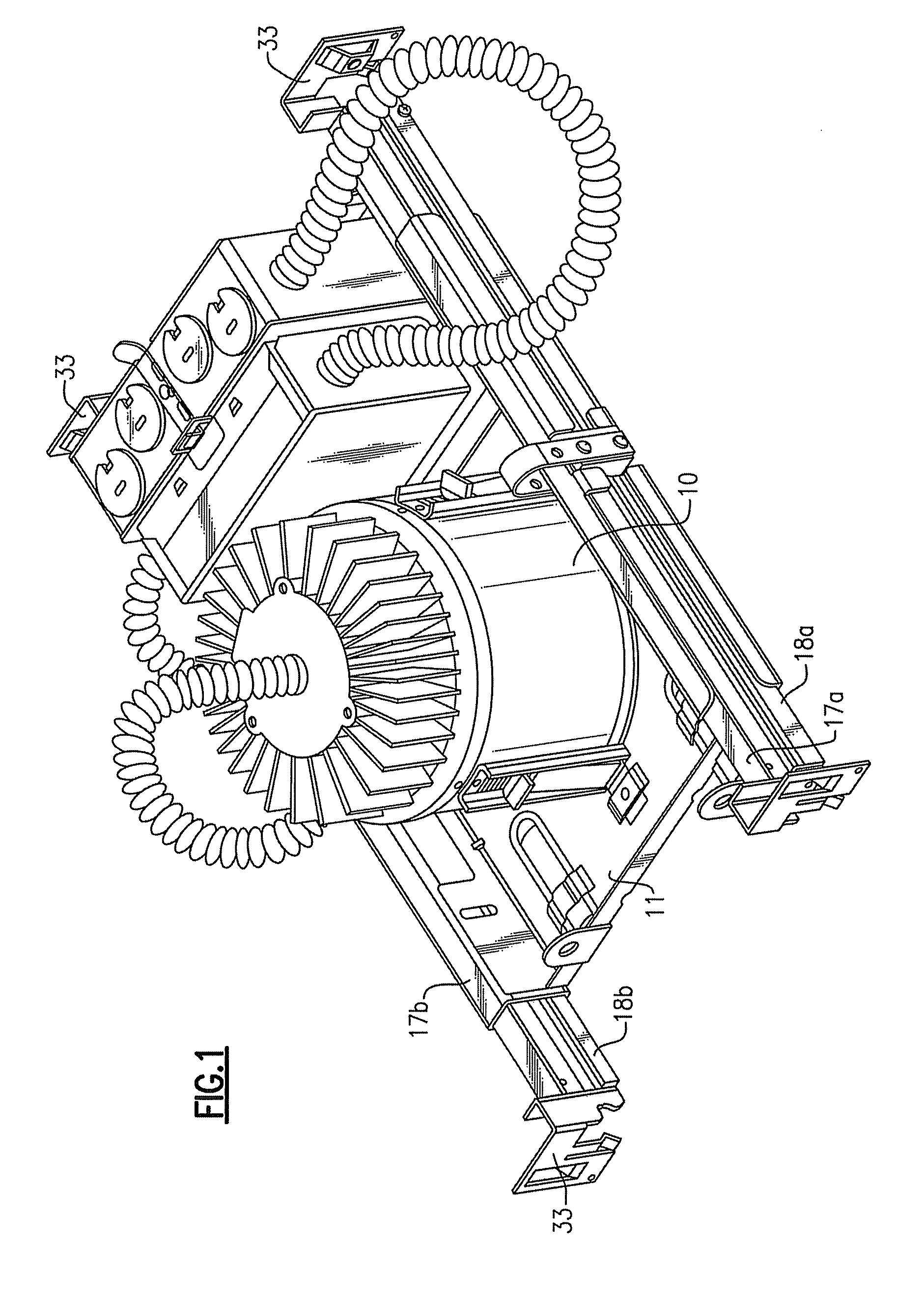
[0140]FIG. 1 depicts a lighting fixture according to the present inventive subject matter. This embodiment includes a light emitting element 10 mounted on a light emitting element mounting assembly 11 which includes a first set of rails comprising a first rail 17a and a second rail 18a, and a second set of rails comprising a first rail 17b and a second rail 18b. Each of the rails includes a bracket 33.

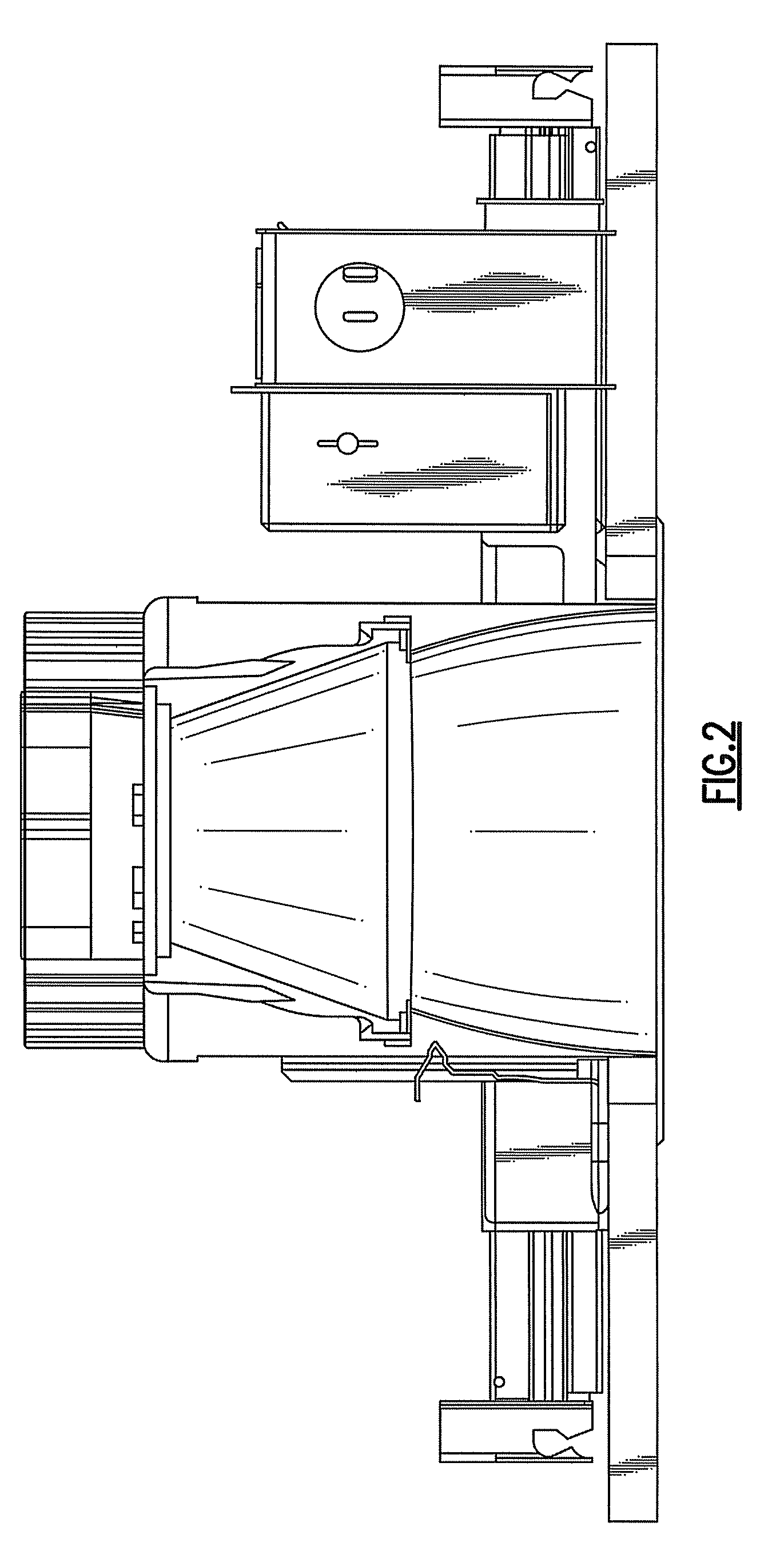
[0141]FIG. 2 is a cutaway view of the lighting fixture depicted in FIG. 1.

second embodiment

[0142]FIG. 3 depicts a lighting fixture according to the present inventive subject matter, which includes a light emitting element mounting assembly 11 (and two sets of rails 17a, 18a and 17b, 18b), and the light emitting element mounting assembly 11 includes a receiving structure in the form of an opening 22. The embodiment depicted in FIG. 3 is similar to the embodiment shown in FIG. 1, except that in the embodiment shown in FIG. 1, a light emitting element (in the form of a can 10) is positioned within the opening 22.

third embodiment

[0143]FIG. 4 depicts a light fixture according to the present inventive subject matter, which includes a light emitting element mounting assembly 12 with a light emitting element 13.

[0144]FIG. 5 is a close-up view of a portion of the third embodiment, which shows a spring clip 14 and a clip engagement structure 15 which has a plurality of clip engagement regions in the form of slots 16. In this embodiment, the spring clip 14 is mounted on the light emitting element mounting assembly 11 and the clip engagement structure is mounted on the light emitting element 10.

[0145]FIG. 6 depicts a profile of an embodiment of a rail according to the present inventive subject matter.

[0146]FIG. 7 depicts profiles of an embodiment of mated rails 17 and 18 according to the present inventive subject matter.

[0147]FIG. 8 depicts an isometric view of the mated rails 17 and 18 shown in FIG. 7.

[0148]FIG. 9 depicts an embodiment which includes a first rail 17 and a second rail 18.

[0149]FIG. 10 is a close-up...


PUM


Abstract

A lighting fixture comprises a mounting assembly and two rails. At least one of the rails is slidable relative to the mounting assembly. The rails are each extruded, and have profiles which are substantially similar to each other. Each rail has a male component which fits within a female component of the other. Also, a fixture comprising a mounting assembly comprising an opening through which a light engine housing can be inserted, and (1) a spring clip and / or (2) a clip engagement structure. Also, a fixture comprising a mounting assembly, a first set of rails, and a supplemental rail. The supplemental rail is slidable relative to the light emitting element mounting assembly. Also, a fixture comprising a mounting assembly, a set of rails, and an engagement element having a first portion being in contact with a first rail and a second portion in contact with the second rail.

Description

CROSS-REFERENCE TO RELATED APPLICATIONS[0001]This application is a continuation-in-part of U.S. Design patent application No. 29 / 279,589, filed May 3, 2007 (now U.S. Design Pat. No. D571,944 issued Jun. 24, 2008).[0002]This application is a continuation-in-part of U.S. Design patent application No. 29 / 284,294, filed Sept. 5, 2007 (now U.S. Design Pat. No. D596,330 issued Jul. 14, 2009).[0003]This application claims the benefit of U.S. Provisional Patent Application No. 60 / 916,030, filed May 4, 2007, the entirety of which is incorporated herein by reference.FIELD OF THE INVENTION(S)[0004]The present inventive subject matter relates to a lighting fixture. In some embodiments, as discussed below, the present inventive subject matter relates to a downlight lighting fixture (e.g., a “can” lighting fixture, also referred to as a recessed lighting fixture).BACKGROUND OF THE INVENTION(S)[0005]A large proportion (some estimates are as high as twenty-five percent) of the electricity generated...

Claims


Application Information

Patent Timeline
Patent Type & Authority Patents(United States)
IPC IPC(8): F21V15/00
CPCF21V21/048F21S8/026F21V29/77
Inventor PICKARD, PAUL KENNETHLAY, JAMES MICHAELTROTT, GARY DAVID
Owner IDEAL IND LIGHTING LLC
Features
  • Generate Ideas
  • Intellectual Property
  • Life Sciences
  • Materials
  • Tech Scout
  • Unparalleled Data Quality
  • Higher Quality Content
  • 60% Fewer Hallucinations
Learn More