Dual spring probe coaxial contact system

a coaxial contact and spring probe technology, applied in the direction of coupling contact members, coupling device connections, coupling devices with two parts, etc., to achieve the effect of minimizing losses

Active Publication Date: 2011-07-05
ITT MFG ENTERPRISES LLC
View PDF16 Cites 60 Cited by
  • Summary
  • Abstract
  • Description
  • Claims
  • Application Information

AI Technical Summary

Benefits of technology

[0003]In accordance with one embodiment of the invention, a coaxial connector system is provided which enables first and second connectors with coaxial contacts to mate with only a short insertion distance of one connector into the other, and which enables the close control of connector characteristic impedance along the connector length to minimize losses. A first connector has c...

Problems solved by technology

This kind of contact arrangement requires that one contact be inserted deeply within the other, which is a disadvantage in many applic...

Method used


Image

  • Dual spring probe coaxial contact system
  • Dual spring probe coaxial contact system

Examples


Embodiment Construction

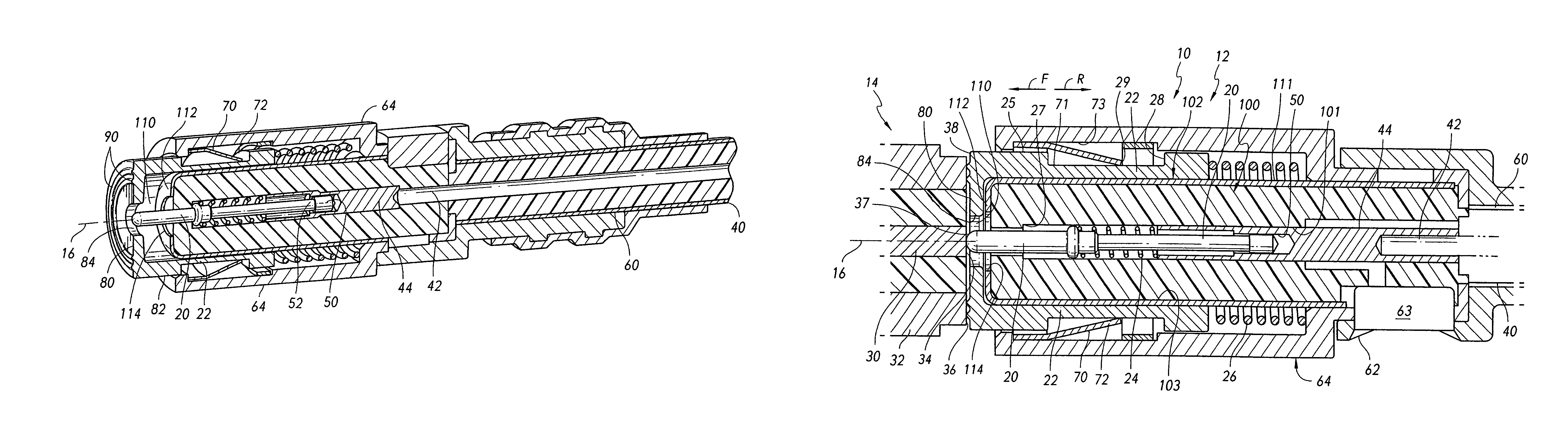
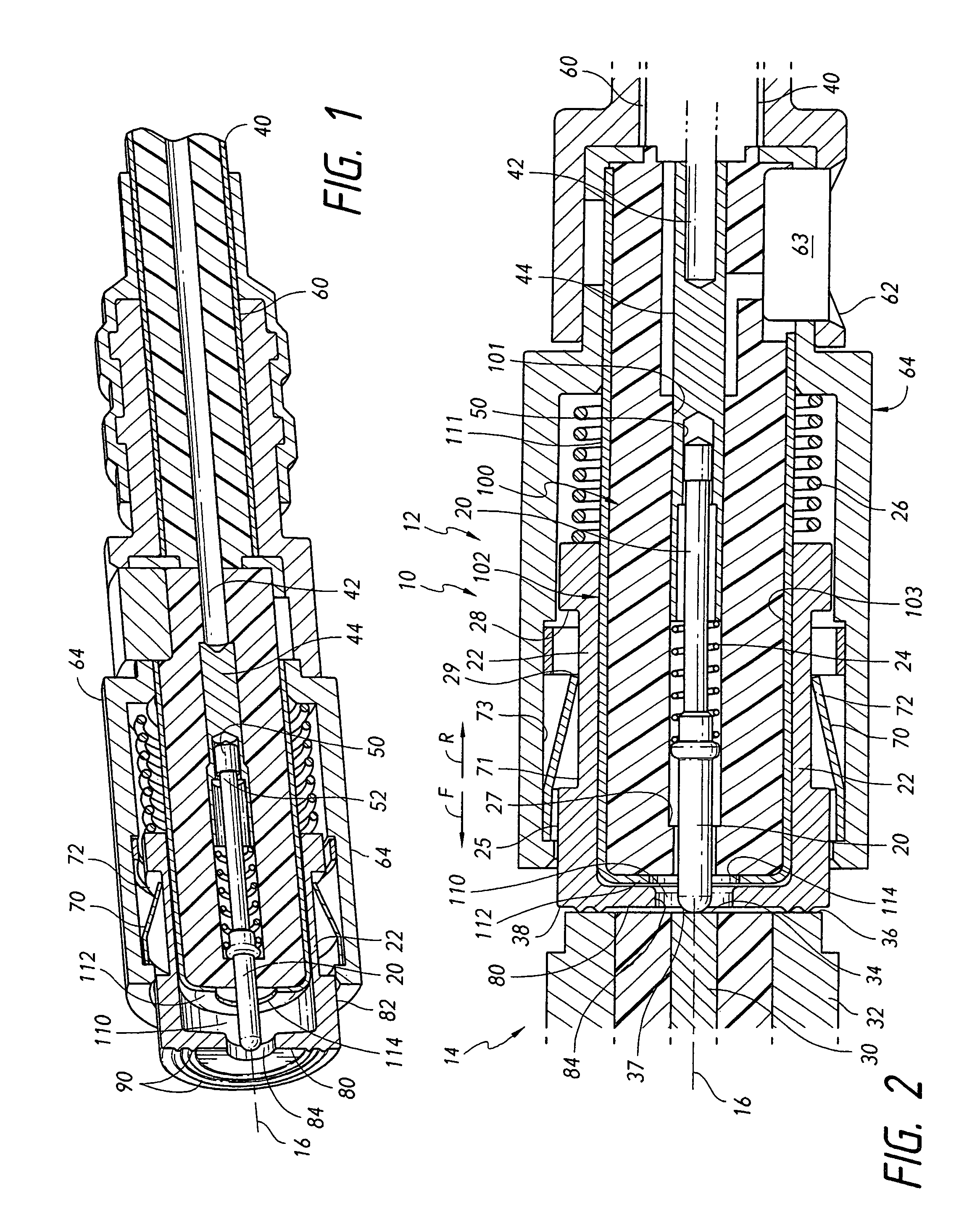
[0008]FIG. 2 shows a connector system 10 that includes first and second coaxial connectors 12, 14 that lie on an axis 16 that extends in front F and rear R directions. Each connector is symmetric about the axis. The first connector 12 includes a movable center or inner contact 20, and a movable outer contact 22. The inner and outer contacts are biased forwardly by separate helical wire compression springs 24, 26. Both compression springs extend around the axis and thereby avoid a sudden change in characteristic impedance. A center stop 27 limits forward movement of the inner contact, and an outer stop 28 that can abut a clip tab rear end 29, limits outer contact forward movement. The second connector 14 has stationary inner and outer contacts 30, 32 whose rear ends form contact pads 34, 36. The contact pads 34, 36 are preferably flush with each other, and the moveable contact front ends are flush when their front end 37, 38 both engage the contact pads. FIG. 2 shows the two connecto...


PUM


Abstract

A connector system includes first and second mateable connectors (12, 14) with coaxial contacts, wherein the first connector has movable center and outer contacts (20, 22) that are each biased forward by a separate spring (24, 26) to engage stationary contact pads (34, 36) of the mating second connector. A stationary tubular insulator (100) surrounds much of the movable center contact, and a stationary sheet metal shield (102) lies around the tubular insulator and within the outer contact. The front end of the movable outer contact forms an internal flange (80) with a hole (84) that allows the front end of the movable center contact to pass through. The shield front-end has an internal flange (112) that lies between the front end of the tubular insulator and the movable outer contact internal flange, to maintain a constant impedance through out the first connector.

Description

BACKGROUND OF THE INVENTION[0001]Connectors often includes coaxial contacts to carry high frequency signals (e.g. over 1 MHz). One design uses long pin-and-socket contacts to assure good electrical engagement between the mating contacts. This kind of contact arrangement requires that one contact be inserted deeply within the other, which is a disadvantage in many applications. Also, the insertion of one contact deeply into another can alter the characteristic impedance along the contacts and result in losses.[0002]A contact arrangement for connector that include at least one set of coaxial contacts, which enabled mating with only a short distance of movement of one contact into the other one, and which enabled close control of the characteristic impedance along the connector, would be of value.SUMMARY OF THE INVENTION[0003]In accordance with one embodiment of the invention, a coaxial connector system is provided which enables first and second connectors with coaxial contacts to mate...

Claims


Application Information

Patent Timeline
IPC IPC(8): H01R9/05
CPCH01R13/2421H01R13/65802H01R24/44H01R13/6583
Inventor HYZIN, PETER J.FINONA, MICHAEL SANTOS
Owner ITT MFG ENTERPRISES LLC
Why Eureka
Try Eureka