
Disk drive biasing refresh zone counters based on write commands

a technology of write command and disk drive, applied in the field of disk drives, can solve problems such as data errors, data is no longer recoverable, and the magnetic field emanating from the disk surface will deteriora

Inactive Publication Date: 2011-07-05
WESTERN DIGITAL TECH INC
View PDF109 Cites 145 Cited by
  • Summary
  • Abstract
  • Description
  • Claims
  • Application Information

AI Technical Summary

Problems solved by technology

The hysteresis of the magnetic grains is not permanent meaning that over time the grains will orientate into random directions (magnetic entropy) until the magnetic field is no longer sensed reliably (leading to data errors during reproduction).
Eventually, the magnetic field emanating from the disk surface will deteriorate to the point that the data is no longer recoverable.

Method used


Image

  • Disk drive biasing refresh zone counters based on write commands
  • Disk drive biasing refresh zone counters based on write commands
  • Disk drive biasing refresh zone counters based on write commands

Examples


Embodiment Construction

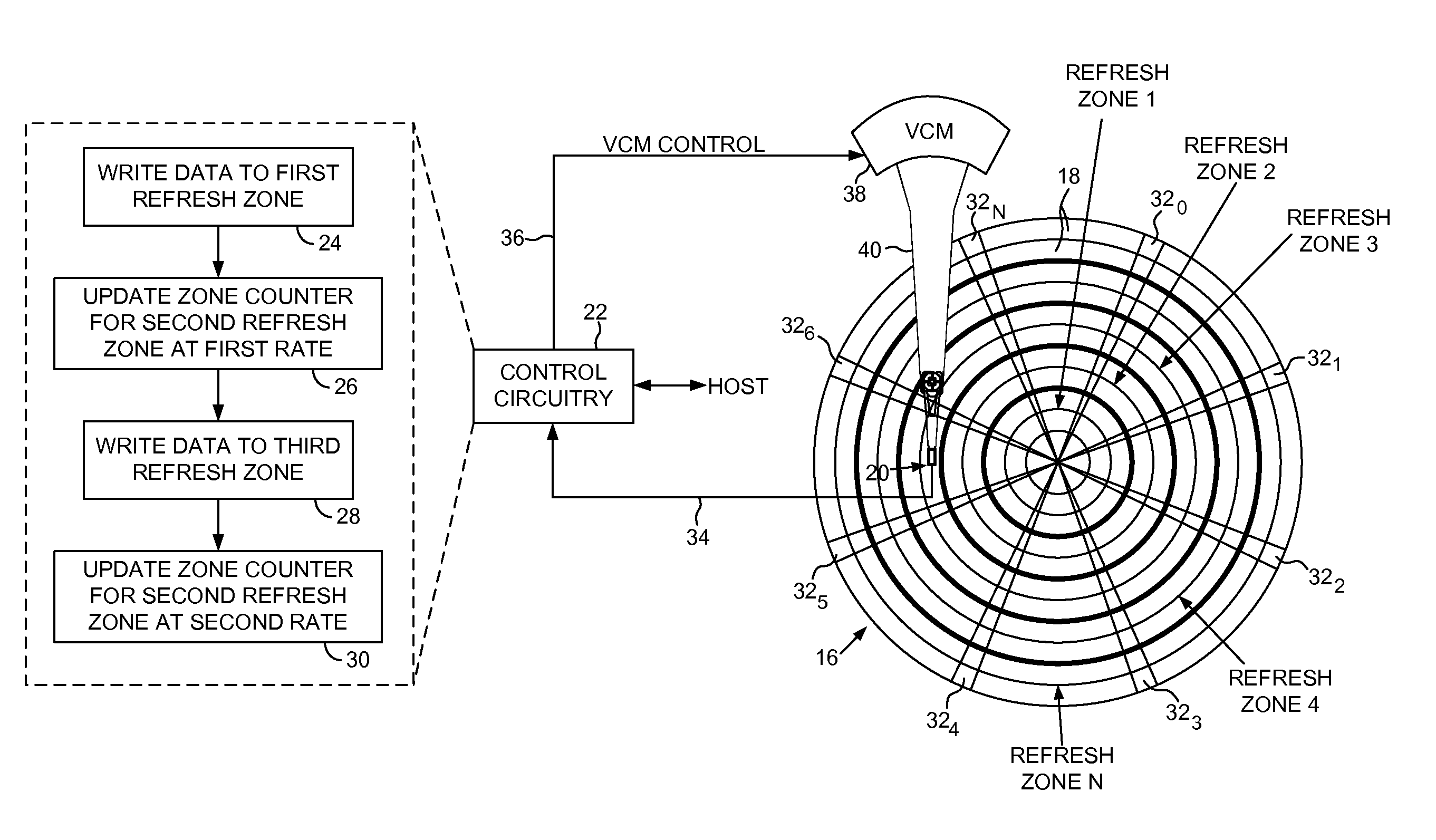
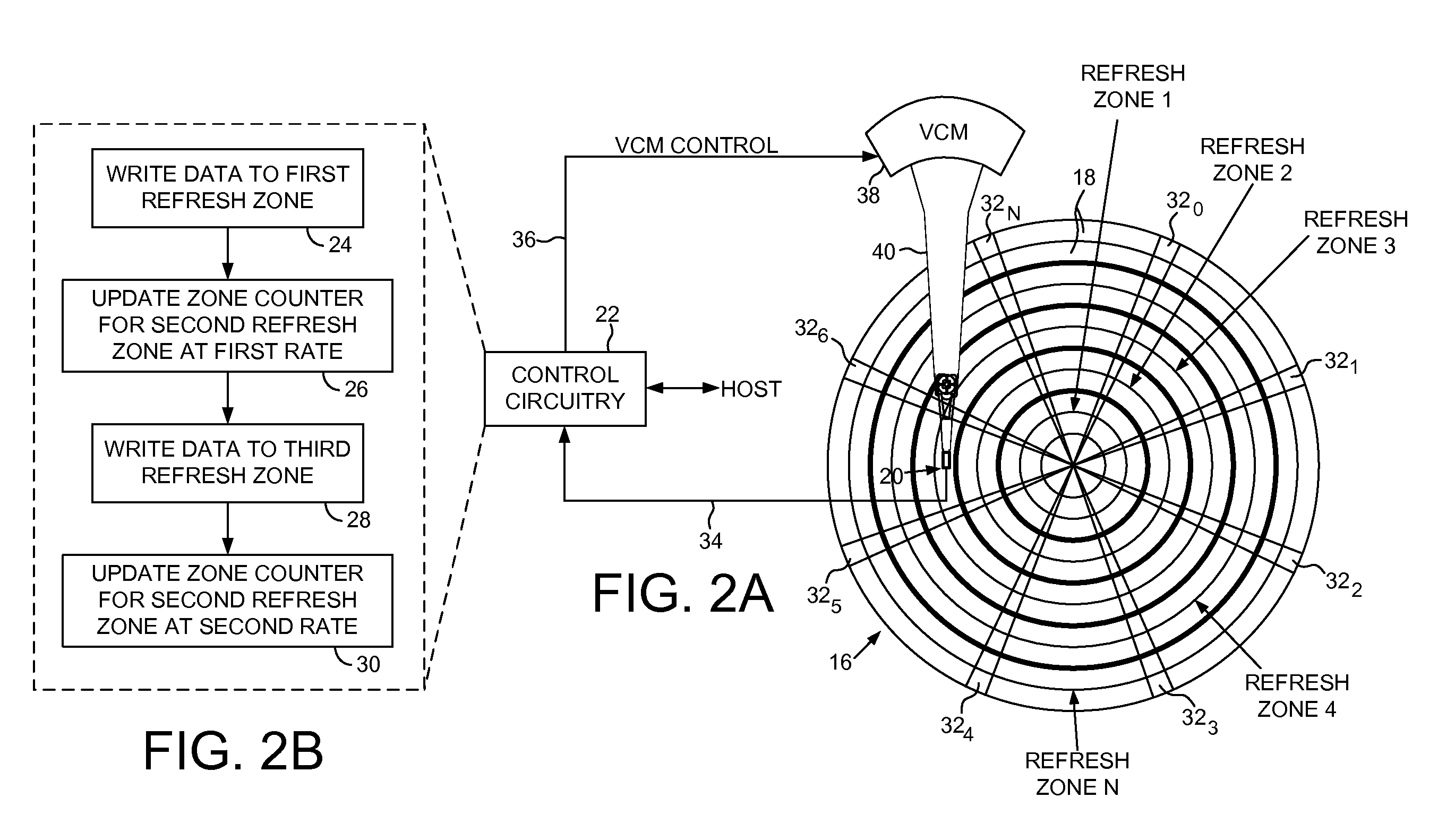
FIG. 2A shows a disk drive according to an embodiment of the present invention comprising a disk 16 having a plurality of tracks 18, and a head 20 actuated over the disk 16. A plurality of refresh zones are defined, wherein each refresh zone corresponds to a plurality of the tracks 18. The disk drive further comprises control circuitry 22 operable to execute the flow diagram of FIG. 2B, wherein data is written to a first refresh zone (step 24), and a first zone counter is updated for a second refresh zone at a first rate (step 26). Data is written to a third refresh zone (step 28), and the first zone counter is updated for the second refresh zone at a second rate different than the first rate (step 30).

The zone counters are used to refresh the data stored in the tracks of the corresponding refresh zone. For example, when a zone counter exceeds a threshold, the corresponding refresh zone is refreshed by reading and rewriting the data stored in the tracks. In one embodiment, the data ...


PUM

PropertyMeasurementUnit
ODaaaaaaaaaa
outer diameteraaaaaaaaaa
inner diameteraaaaaaaaaa

Abstract

A disk drive is disclosed comprising a disk comprising a plurality of tracks, and a head actuated over the disk. A plurality of refresh zones are defined, wherein each refresh zone corresponds to a plurality of the tracks. Data is written to a first refresh zone, and a first zone counter is updated for a second refresh zone at a first rate. Data is written to a third refresh zone, and the first zone counter is updated for the second refresh zone at a second rate different than the first rate.

Description

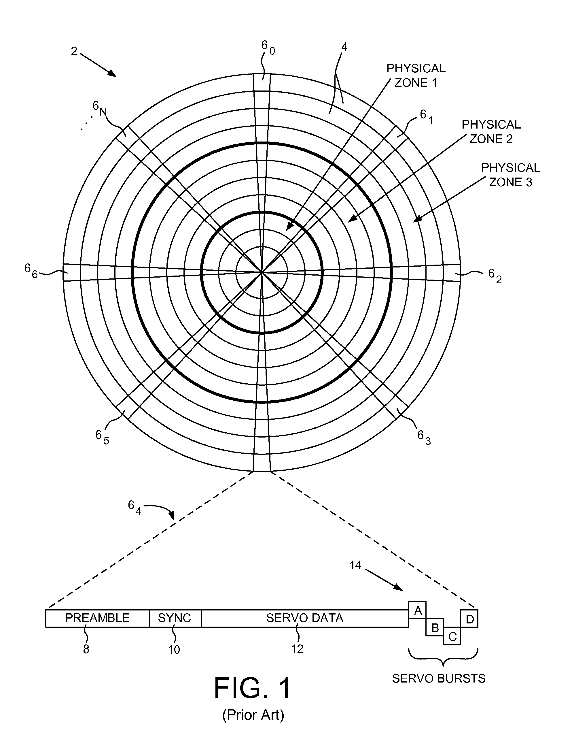
BACKGROUNDDisk drives comprise a disk and a head connected to a distal end of an actuator arm which is rotated about a pivot by a voice coil motor (VCM) to position the head radially over the disk. The disk comprises a plurality of radially spaced, concentric tracks for recording user data sectors and embedded servo sectors. The embedded servo sectors comprise head positioning information (e.g., a track address) which is read by the head and processed by a servo control system to control the velocity of the actuator arm as it seeks from track to track.During a write operation, a current is applied to a write element of the head (e.g., a write coil) to create a magnetic field which magnetizes the surface of the disk by orienting the direction of magnetic grains (e.g., horizontally in longitudinal magnetic recording, or vertically in perpendicular magnetic recording). The orientation of the grains exhibits hysteresis thereby generating their own magnetic field when the write magnetic ...

Claims


Application Information

Patent Timeline
Patent Type & Authority Patents(United States)
IPC IPC(8): G11B27/36
CPCG11B5/012G11B2220/2516G11B2020/1869
Inventor TSAI, CHUN SEIHUYNH, SANGPEI, ANTHONY L.BRUNNETT, DONKASRAEE, JAHANGIR JOHNGIBBONS, KENT W.
Owner WESTERN DIGITAL TECH INC
Learn More