Evaluating the position of a disturbance

a technology detecting disturbances, which is applied in the field of evaluating the position of disturbances, can solve the problems that the known optical time domain reflectometry (otdr) techniques are not well suited to detecting time-varying disturbances and corresponding (albeit attenuated or modified) disturbances

Active Publication Date: 2011-07-05
BRITISH TELECOMM PLC
View PDF175 Cites 13 Cited by
  • Summary
  • Abstract
  • Description
  • Claims
  • Application Information

AI Technical Summary

Problems solved by technology

However, such known Optical Time Domain Reflectometry (OTDR) techniques are not well suited to detecting time-varying disturbances.
Preferably, the optical channel will be in a mechanically coupled relationship to the track, such that movement of the vehicle causes a disturbance along the optical channel.
However, because of the mech

Method used


Image

  • Evaluating the position of a disturbance
  • Evaluating the position of a disturbance
  • Evaluating the position of a disturbance

Examples


Embodiment Construction

Estimating the Position of a Disturbance

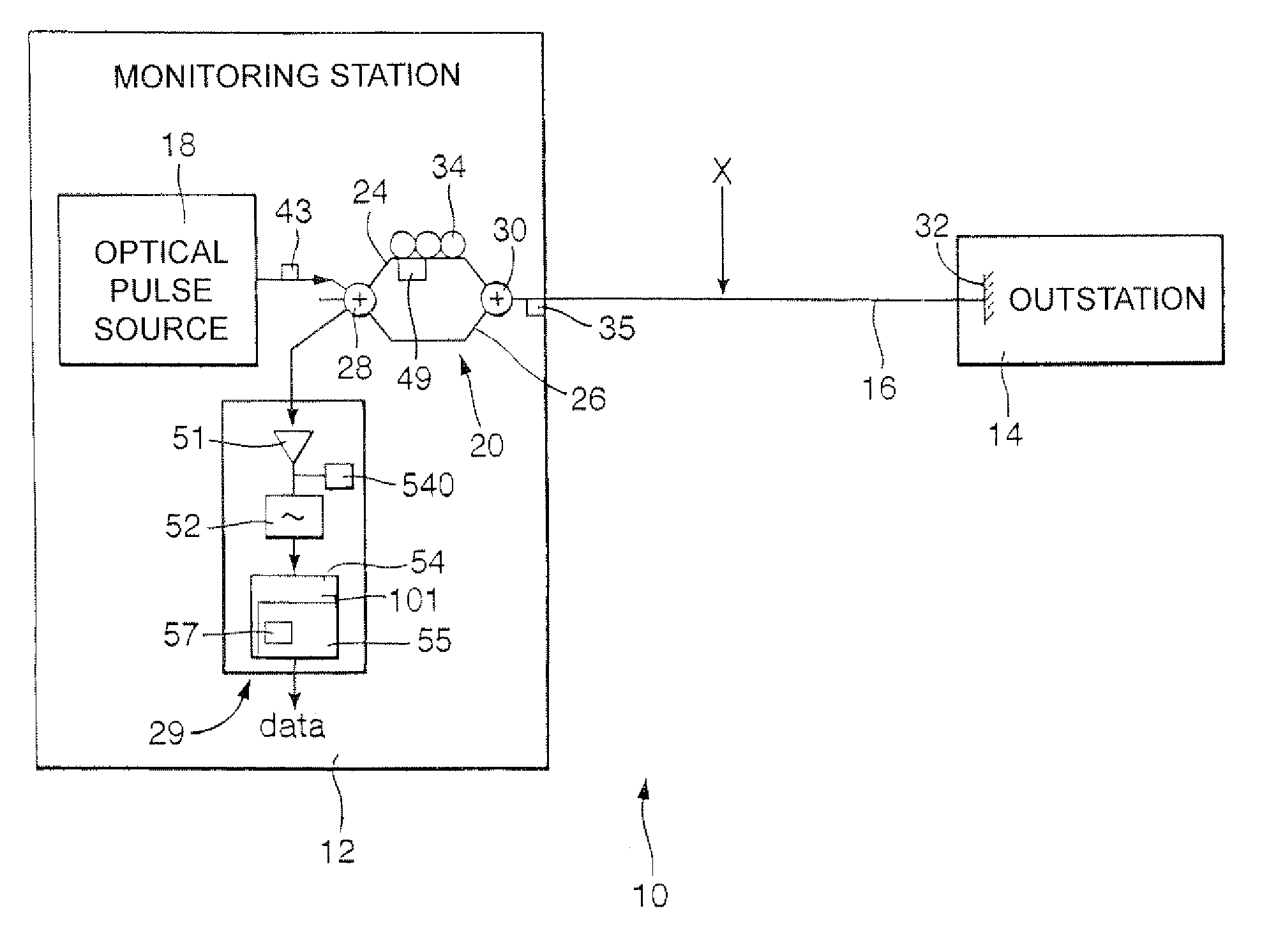
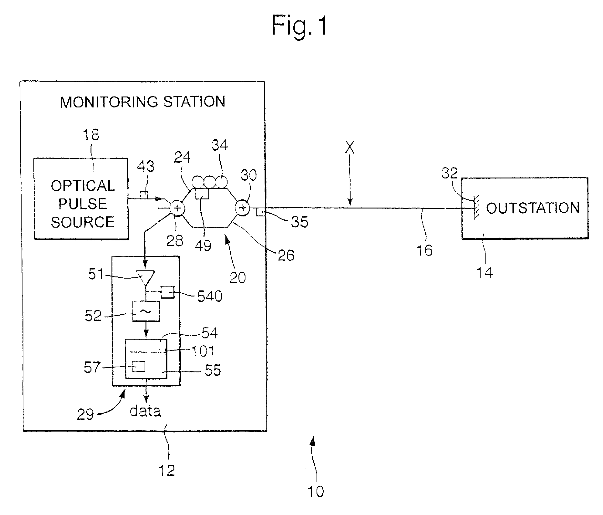
[0033]The monitoring station 12 includes an optical pulse source 18 with a short coherence time (random phase changes in the output providing an irregular component to the signal), the pulse source being driven by a driver unit. Pulses from the optical source 18 are fed to an interferometer stage 20, here a Mach Zhender interferometer with a first path 24 and a second path 26, the paths 24, 26 being coupled at each end by a respective first and second coupling stage 28, 30. For light travelling in the outbound direction, the first coupling stage 28 acts as a directional power (intensity) splitter, channeling light from the optical source 18 to each of the paths 24, 26, the power to each path being shared in a predetermined manner (here, the first coupling stage acts as a 50:50 power splitter, although a different ratio could be used).

[0034]The monitoring station 12 includes an optical pulse source 18 with a short coherence time (random phase c...


PUM


Abstract

The position of a disturbance on an optical link is evaluated, in particular where the disturbance is a time-varying disturbance. An optical time domain reflectometry technique is used in which a series of low coherence test pulses is launched by means of an optical pulse source into an the optical link, and the backscattered return signal is monitored. The test pulses pass through an unbalanced Mach Zhender interferometer with the result that for each test pulse, a pair of time-displaced pulse copies is launched onto the link. The backscattered return signal is passed through the same interferometer, which causes the pulse copies of each pair to become realigned and to interfere with one another. A time-varying disturbance is likely to affect each pulse copy of a pair differently. As a result, an abnormality such as a step is likely to occur in the backscattered signal. From the time position of an abnormality, the distance of the disturbance responsible is evaluated.

Description

[0001]This application is the US national phase of international application PCT / GB2005 / 001269 filed 31 Mar. 2005 which designated the U.S. and claims benefit of GB 0407386.2, dated 31 Mar. 2004, the entire content of which is hereby incorporated by reference.BACKGROUND[0002]1. Technical Field[0003]The present invention relates to a method of and apparatus for evaluating the position of a disturbance on a transmission link, in particular where the disturbance is a time-varying disturbance.[0004]2. Related Art[0005]It is known to estimate the position of an irregularity in a waveguide by launching a test pulse in the waveguide, and monitoring the distributed backscattering of the test pulse so as to detect an abnormality, if any, in the time-dependence of the returned signal. An example of an abnormality could be a step change in the time-dependent amplitude of a return signal. However, such known Optical Time Domain Reflectometry (OTDR) techniques are not well suited to detecting ti...

Claims


Application Information

Patent Timeline
IPC IPC(8): H04L5/12G01D5/353G01M11/00
CPCG01M11/3172G01D5/35303G01M11/00
Inventor HEALEY, PETERSIKORA, EDMUND S R
Owner BRITISH TELECOMM PLC
Why Eureka
Try Eureka