Method for rolling compensation with wheel-mounted sensors

a technology of rolling compensation and sensors, which is applied in the direction of measurement devices, instruments, structural/machine measurement, etc., can solve the problems of erroneous readings, high cost of methods, and introduction of errors for both the car manufacturer and the alignment equipment manufacturer

Active Publication Date: 2011-07-05
HUNTER ENG
View PDF16 Cites 23 Cited by
  • Summary
  • Abstract
  • Description
  • Claims
  • Application Information

AI Technical Summary

Benefits of technology

[0015]Accordingly, it would be advantageous to provide a method for compensating axial misalignment between wheel-mounted alignment sensors and the axis of rotation for an associated wheel which can compensate sensors on all wheels of a vehicle simultaneously without requiring jacking of the vehicle off a supporting surface, and which only requires a wheel rotation through an arc of 60 degrees or less.

Problems solved by technology

While this method is simple, error is introduced if, during the remainder of the alignment procedure, the wheels are allowed to roll away from the rotational position at which the compensation setting was calculated.
However, any foreign objects in, or damage to, the interface between the wheel adapter and the machined provisions on the hub will cause erroneous readings.
This method is expensive for both the car manufacturer and the alignment equipment manufacturer due to the precision machining required.
The above compensation methods are generally useful, but could be time consuming or prone to error.
However, this rolling compensation method has traditionally been restricted to systems using machine-vision technology to observe the motion of the wheel-mounted optical targets during the rolling movement.
These complicated compensation requirements of the hybrid system are a major disadvantage.
These limitations exist because there is no means available at the rear wheel to generate the surface of revolution necessary for machine vision compensation unless an additional fixed reference target is present in the field of view.
Hence, the hybrid system as implemented by the '869 Rogers patent provides no operational compensation advantage over a conventional wheel-mounted alignment systems due to the restricted compensation methods required for the different types of sensors.

Method used


Image

  • Method for rolling compensation with wheel-mounted sensors
  • Method for rolling compensation with wheel-mounted sensors
  • Method for rolling compensation with wheel-mounted sensors

Examples


Embodiment Construction

[0027]The following detailed description illustrates the invention by way of example and not by way of limitation. The description enables one skilled in the art to make and use the present disclosure, and describes several embodiments, adaptations, variations, alternatives, and uses of the present disclosure, including what is presently believed to be the best mode of carrying out the present disclosure.

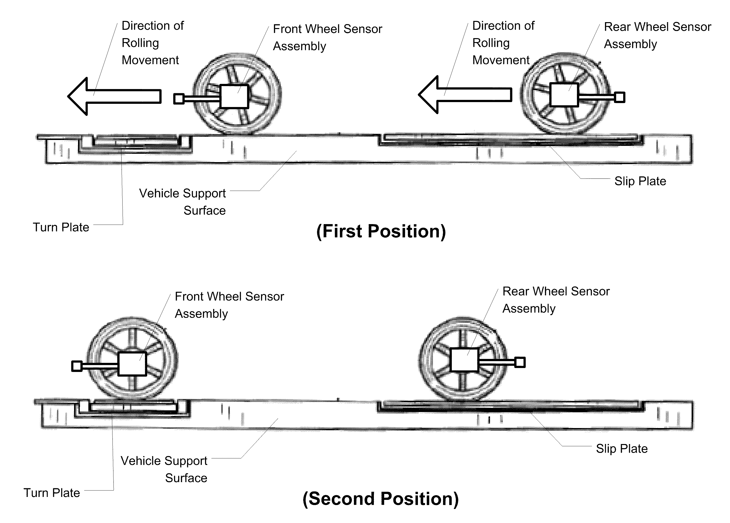
[0028]The present disclosure provides a method for compensating axial misalignment between active, wheel-mounted alignment sensors and an axis of rotation for a wheel on which the sensor is mounted by obtaining sensor readings over a wheel rotational arc of less than 180 degrees, and preferably over an arc of 60 degrees or less, such as shown in FIGS. 5A and 5B. The typical active wheel-mounted alignment sensor incorporates at least a wheel rotation encoder, a camber angle transducer, and a toe angle transducer, and freely rotates about an axis of rotation as the wheel is rotated, m...


PUM


Abstract

A method for compensating axial misalignment between wheel-mounted alignment sensors and an axis of rotation for an associated wheel. The method compensates sensors mounted to each wheel of a vehicle simultaneously, without requiring jacking of the vehicle wheels above a supporting surface, and which only requires wheel rotational movement over an arc of 60 degrees or less. The method utilizes measurements of a change in a wheel toe angle and measurements of a change in a wheel camber angle, during a measured rotational movement of the wheel, to identify sinusoidal variation in the respective toe and camber angles during the wheel's rotational movement, from which a measure of axial misalignment between the wheel-mounted alignment sensor axis of rotation and the wheel axis of rotation is identified.

Description

CROSS-REFERENCE TO RELATED APPLICATIONS[0001]The present application is related to, and claims priority from, U.S. Provisional Patent Application Ser. No. 61 / 095,356 filed on Sep. 9, 2008, and which is herein incorporated by reference.STATEMENT REGARDING FEDERALLY SPONSORED RESEARCH[0002]Not Applicable.BACKGROUND OF THE INVENTION[0003]The present invention is related generally to vehicle wheel alignment systems, and in particular, to a method for compensating for axial misalignment between wheel-mounted alignment sensors and the wheel axis of rotation by rolling the wheel-mounted sensors together with the associated vehicle wheels about a limited range of movement.[0004]In any wheel alignment system the orientation of the axis of rotation of the vehicle wheels must be determined before alignment angles of the wheels can be calculated. In an ideal world, the alignment system sensors would be mounted to the wheels such that they would be perfectly lined up with the axis of rotation of...

Claims


Application Information

Patent Timeline
Patent Type & Authority Patents(United States)
IPC IPC(8): G01M1/38
CPCG01B11/2755G01B2210/14G01B2210/22G01B2210/26G01B2210/306
Inventor BURNS, LEIGH R.STIEFF, MICHAEL T.MCCLENAHAN, JAMES W.
Owner HUNTER ENG
Why Eureka
Try Eureka