Wheel positioning measuring device

A technology for wheel positioning and measuring device, which is applied in the direction of measuring device, optical device, instrument, etc., can solve the problems of insufficient accuracy, narrow viewing angle, delayed processing speed, etc., and achieves the effect of fast processing speed

Inactive Publication Date: 2008-05-14
YASAKA SEIKI
View PDF3 Cites 23 Cited by
  • Summary
  • Abstract
  • Description
  • Claims
  • Application Information

AI Technical Summary

Problems solved by technology

However, since the plane laser light is emitted obliquely instead of reaching the tire horizontally, multiple contour lines formed on the sidewall of the tire are integrally detected by a single image receiver, so the viewing angle is narrow, resulting in measurement accuracy not enough
[0009] The method of wheel alignment using the contour La in the above conventional measuring device requires processing (compensation), e.g. using a mean filter or similar, which may delay the processing speed

Method used


Image

  • Wheel positioning measuring device
  • Wheel positioning measuring device
  • Wheel positioning measuring device

Examples


Embodiment Construction

[0039] The wheel alignment measuring device of the present invention (hereinafter referred to simply as the measuring device) will be described with reference to the accompanying drawings.

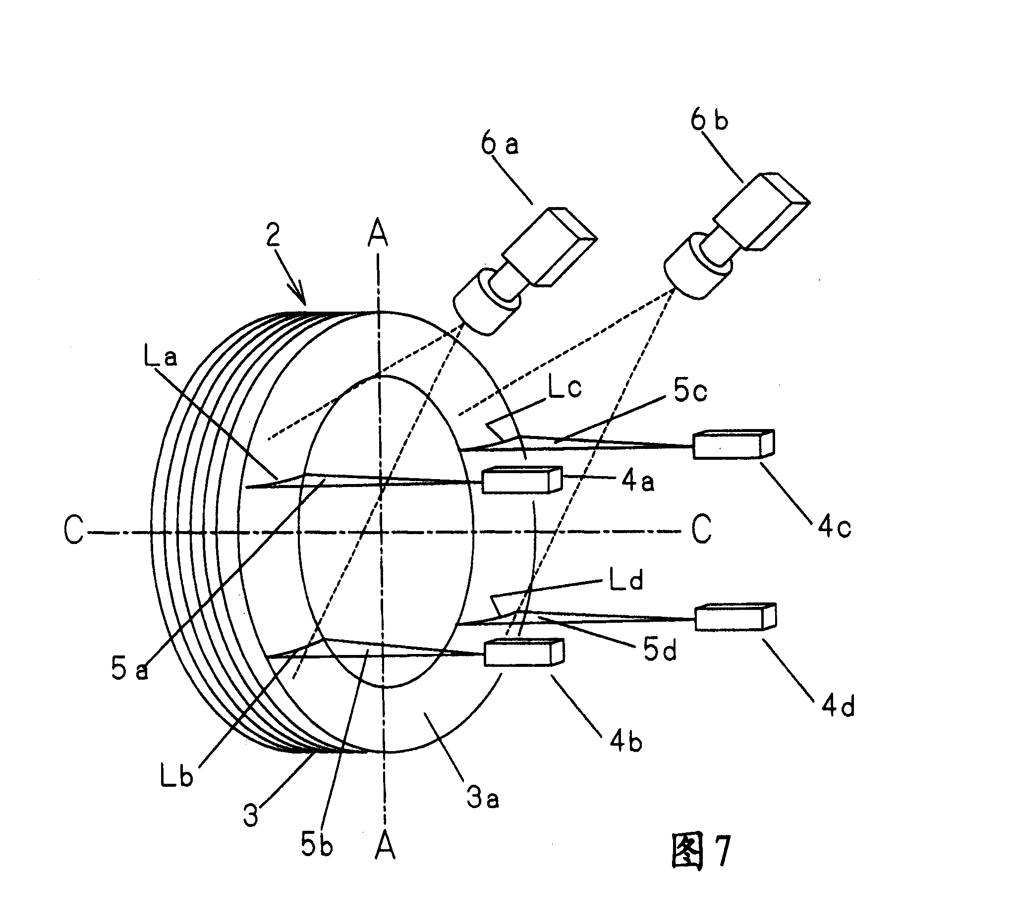
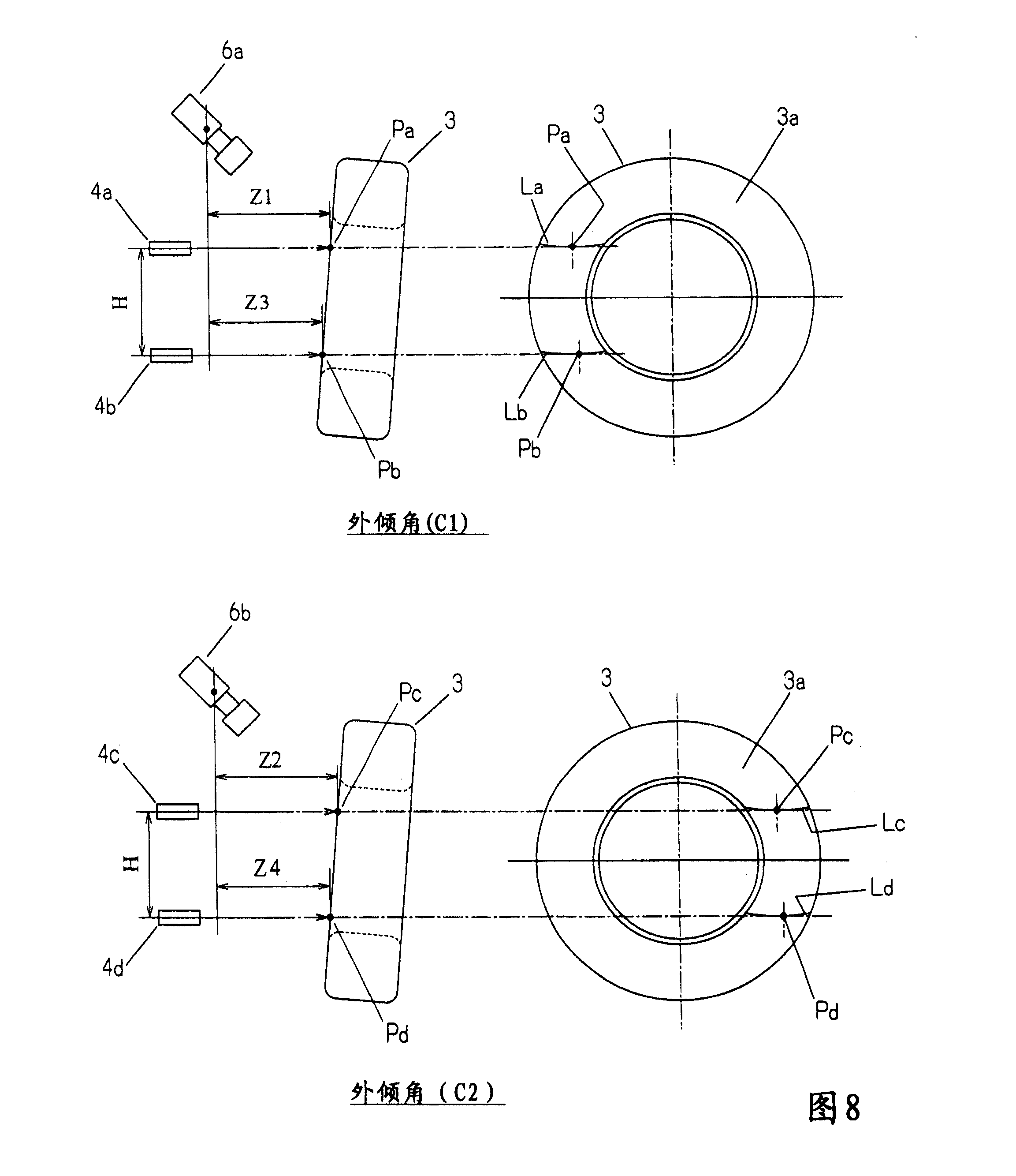
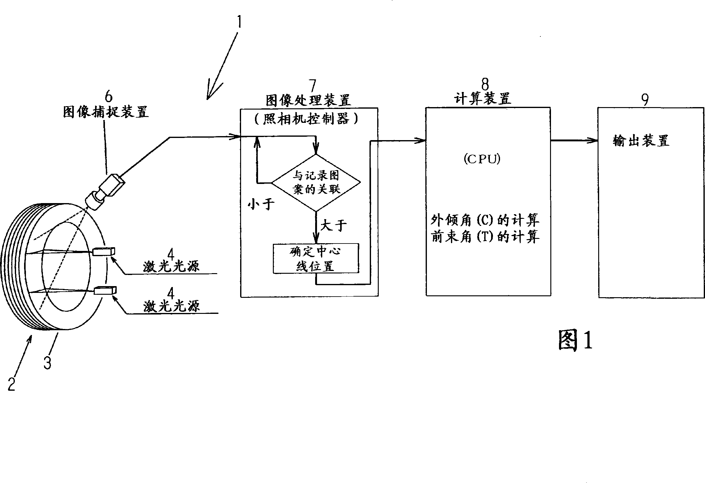
[0040] Figure 1 shows a block diagram of an embodiment of a measuring device. As shown in Figure 1, the measurement device 1 includes a pair of laser light sources 4 for emitting laser beams to the outside of the wheel to form an illuminated contour line thereon, and also includes an image capture device 6 for acquiring the contour line as a measurement image, and including image processing means 7 for determining and recording centerline position data of each contour line obtained by comparing the contour line of the captured image with a plurality of contour lines of the recorded image from the selected image, so as to select and capture the image therefrom The image with a certain or higher correlation also includes calculation means 8 for calculating the wheel alignment status on the b...


PUM


Abstract

The invention relates to a non-contact type wheel positioning and measuring device, which has a simple structure and can measure the toe-in angle and the camber angle with high accuracy. The device comprises a pair of laser sources used for horizontally emitting a beam of laser to the side of the wheel, the pair of laser sources are vertically arranged and separated from each other so as to form two vertical and mutually separated illuminating outline patterns; a pattern catching device which is arranged at the outer side of the laser sources and at a same face with the laser sources so as to catch the outline patterns which is taken as the measured images; an image processor which is used for determining and recording the midline position data of each illuminating outline pattern, the midline position data are images caught by the image catching device and comprise outlines, and each prior recorded image which comprises outline pattern, compared with the caught images, the selected recorded images which comprise the outline patterns have a certain degree of or higher relativity; and a calculating device which gains the position of the wheel through calculating the recorded midline position data.

Description

Background of the invention [0001] The invention relates to a vehicle wheel alignment measuring device which does not contact the wheel. [0002] The vehicle must have its wheel alignment adjusted within the proper range to drive and operate safely and stably. In general, the terms "toe" and "camber" are used to indicate wheel alignment. Toe indicates the angle of inclination of the wheel relative to the direction of travel of the vehicle when viewed directly from above. If the wheel is toe in, this angle is called "Toe angle". If the wheel is tilted outward, this angle is called "toe angle". Camber indicates the angle of inclination of the wheel at the contact point with respect to the vertical plane outward or inward when viewed from the front or rear. If the wheel Toe in, it is called "negative camber". If the wheel is toe out, it is called "positive camber". Checking whether the wheel alignment of the vehicle is adjusted in the proper range is usually done by measuring th...

Claims


Application Information

Patent Timeline
Patent Type & Authority Applications(China)
IPC IPC(8): G01B11/26G01B11/275
CPCG01B11/275G01B2210/12G01B2210/26
Inventor 高田正伸后藤康弘
Owner YASAKA SEIKI
Why Eureka
Try Eureka