Calculating distortion summaries for circuit distortion analysis

a circuit and distortion analysis technology, applied in the field of circuit analysis, can solve the problems of inability to separate, generally requires high-order device derivatives, and the application of volterra series has typically been limited to simple models and simple circuits

Active Publication Date: 2011-07-12
CADENCE DESIGN SYST INC
View PDF13 Cites 2 Cited by
  • Summary
  • Abstract
  • Description
  • Claims
  • Application Information

AI Technical Summary

Benefits of technology

[0006]In one embodiment of the present invention, a method of analyzing distortion in a circuit includes: determining an operating point for the circuit, where the circuit has a linear offset and a nonlinear offset for analyzing distortion at the operating point; determining first-order output values by using the linear offset to relate an input having an input frequency with the first-order output values; specifying one or more devices for analyzing the circuit; determining first nonlinear-offset values for the one or more devices at twice the input frequency and at a zero frequency by evaluating the nonlinear offset at values based on the first-order output values; determining second-order output values for the one or more devices at twice the input frequency and at the zero frequency by using the linear offset to relate the second-order output values with the first nonlinear-offset values; determining second nonlinear-offset values for the one or more devices at the input frequency by evaluating the nonlinear offset at values based on the first order-order output values and the second-order output values; determining third-order output values for the one or more devices at the input frequency by using the linear offset to relate the third-order output values with the second nonlinear-offset values; and saving at least some values based on the output values.
[0009]In another embodiment of the present invention, a method of analyzing distortion in a circuit includes: determining an operating point for the circuit, where the circuit has a linear offset and a nonlinear offset for analyzing distortion at the operating point; determining first-order output values by using the linear offset to relate an input having a first frequency and a second frequency with the first-order output values; specifying one or more devices for analyzing the circuit; determining nonlinear-offset values for the one or more devices at a difference between the first frequency and the second frequency by evaluating the nonlinear offset at values based on the first order-order output values; determining contributions to distortion for the one or more devices by projecting the nonlinear-offset values based on the difference between the first frequency and the second frequency; and saving at least some values based on the contributions to distortion for the one or more devices.

Problems solved by technology

While in general such a separation is not possible for most nonlinear effects because of cross terms between devices, insights on distortion dependency on nonlinearity in a single device can still be obtained by conducting some heuristic analysis.
A drawback of the Volterra method is that it generally requires high order device derivatives, which usually are not provided by device models used in real design simulations.
As a result, the application of Volterra series has typically been limited to simple models and simple circuits.
In general, current methods do not adequately model circuit distortion in terms of contributions from separate device elements.

Method used


Image

  • Calculating distortion summaries for circuit distortion analysis
  • Calculating distortion summaries for circuit distortion analysis
  • Calculating distortion summaries for circuit distortion analysis

Examples


Embodiment Construction

1. Introduction

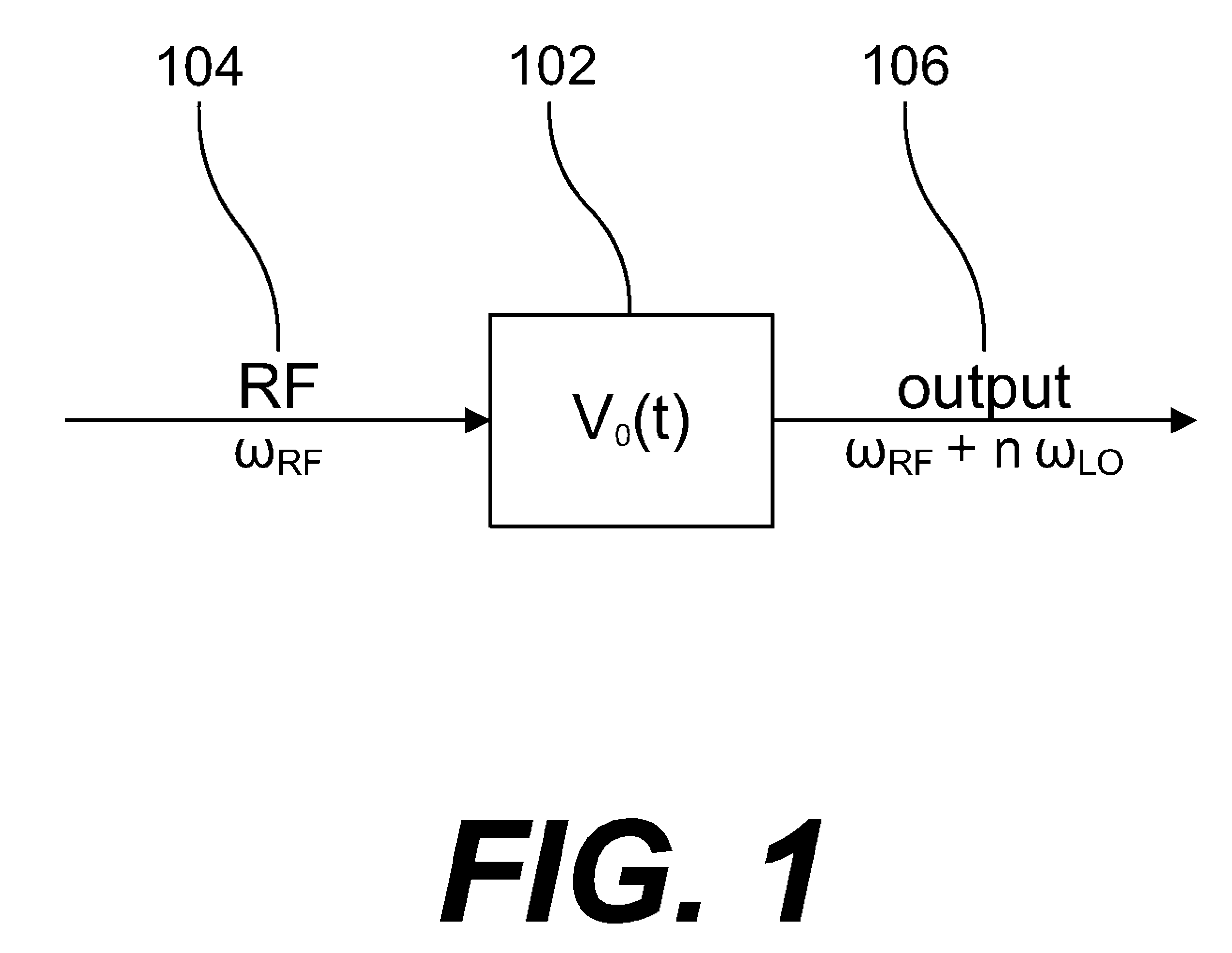
[0021]FIG. 1 shows a system 102 (e.g., a circuit model) that receives an RF input 104 with an input frequency ωRF and produces an output 106 where the input frequency has been modulated by the system (e.g., shifted by a multiple of the LO (Local Oscillator) frequency ωLO. Under non-ideal conditions, the output 106 includes distortions due to the nonlinear effects in the system 102. As described below, the present invention enables quantitative characterizations of how component devices contribute to distortion in the output signal 106. Specific embodiments include calculations for compression distortion and second-order intermodulation products (IM2). This application is related to CALCULATING INTERMODULATION PRODUCTS AND INTERCEPT POINTS FOR CIRCUIT DISTORTION ANALYSIS (application Ser. No. 11 / 303,049, filed Dec. 14, 2005), which is incorporated herein by reference in its entirety.

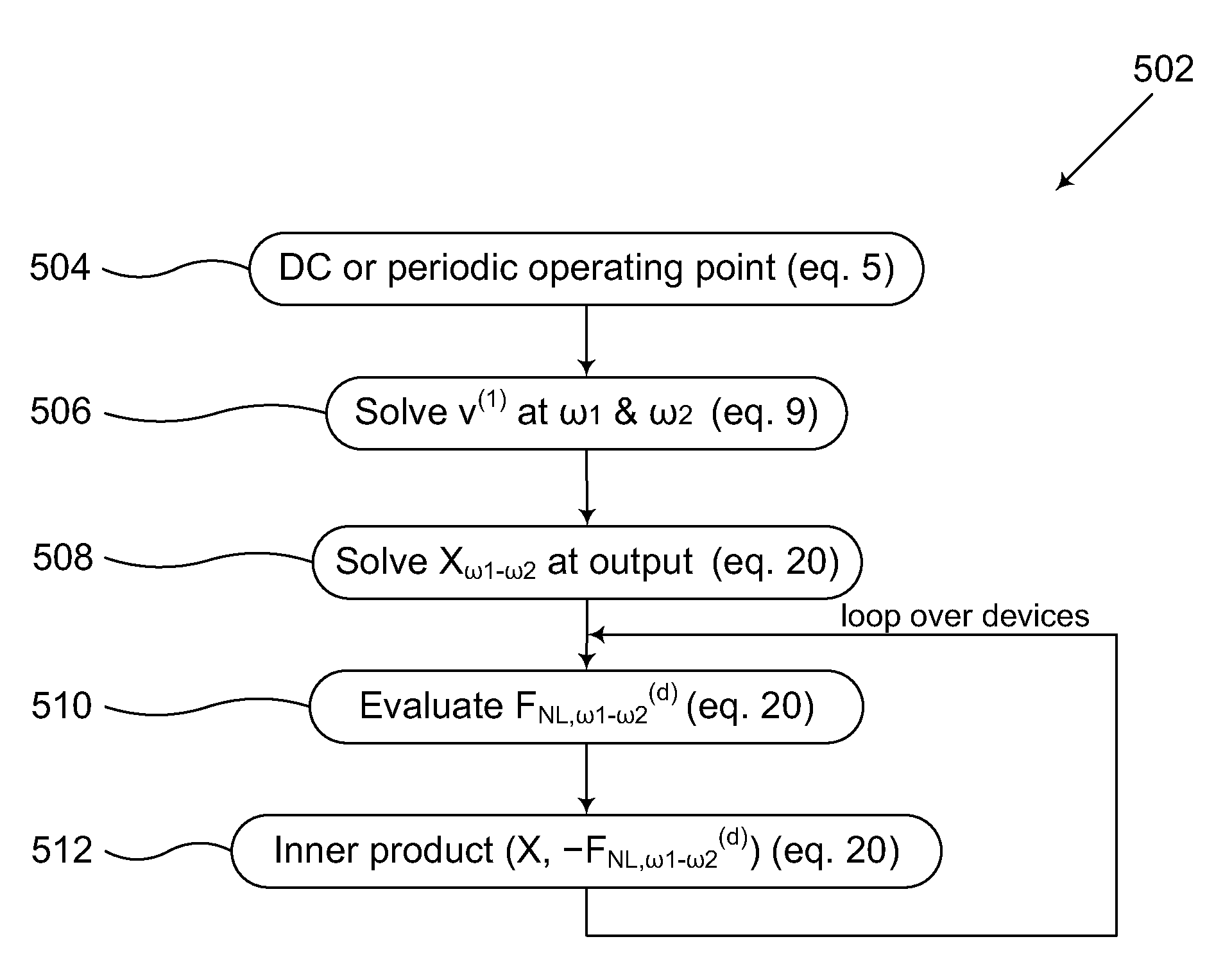
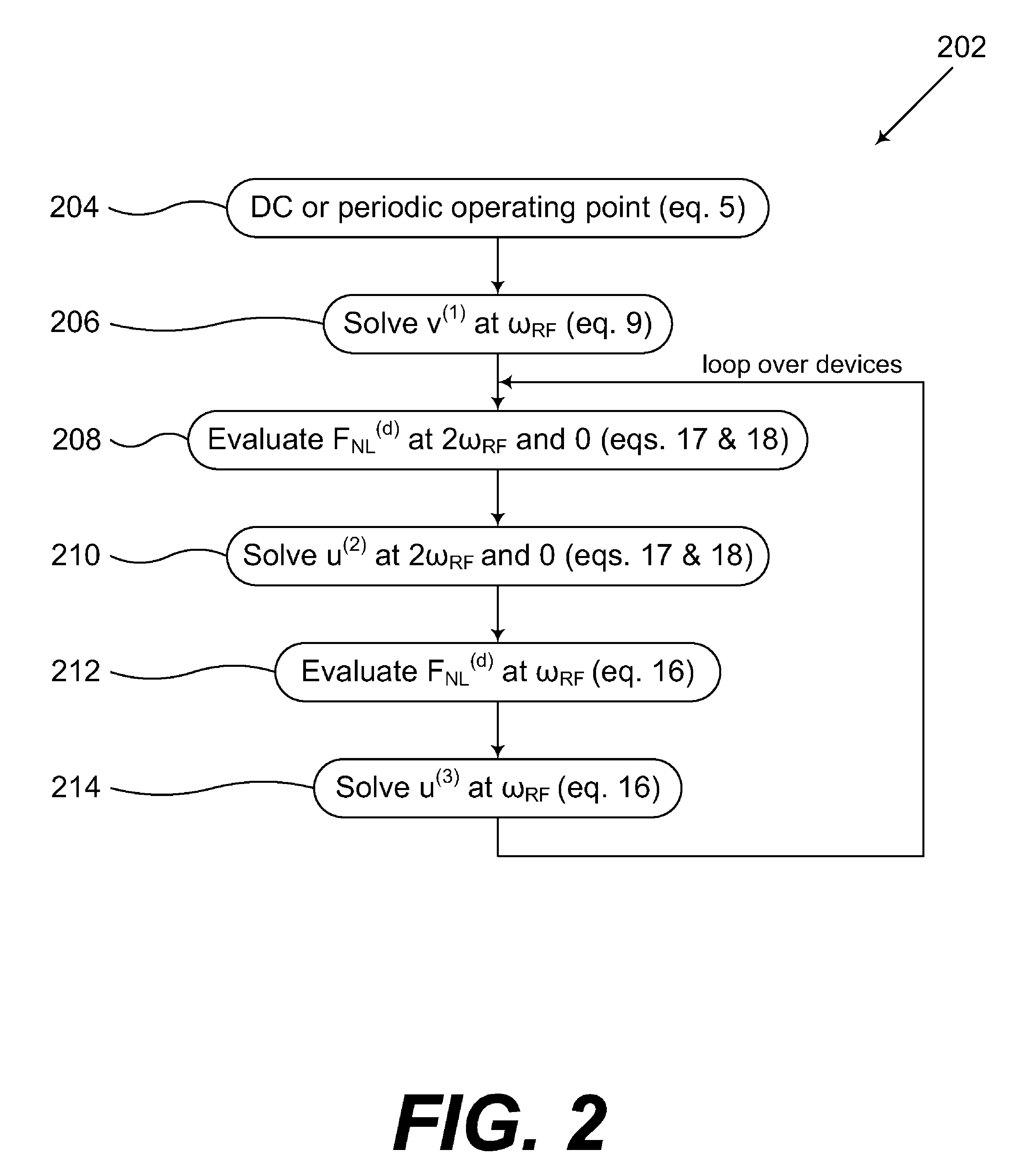
2. Compression Distortion Summary

[0022]The circuit 102 in FIG. 1 has a periodic time-de...


PUM


Abstract

Methods for analyzing circuit distortion based on contributions from separate circuit elements are presented. Local approximations that do not require high-order derivatives of device models are developed near an operating point for calculating distortion summaries including compression summaries and second-order intermodulation (IM2) distortion summaries.

Description

CROSS-REFERENCE TO RELATED APPLICATIONS[0001]This application is a divisional of application Ser. No. 11 / 640,137, filed Dec. 14, 2006, which is incorporated herein by reference in its entirety. This application claims the benefit of U.S. Provisional Application No. 60 / 750,706, filed Dec. 14, 2005, which is incorporated herein by reference in its entirety.BACKGROUND OF THE INVENTION[0002]The present invention relates to the analysis of circuits generally and more particularly to the distortion analysis of analog and RF (Radio Frequency) circuits by calculating distortion contributions of individual circuit elements.[0003]Circuit linearity is a critical specification in analog and RF designs. Intermodulation product and compression are two commonly adopted measures for distortion [6, 11]. As a result, a general methodology for analyzing effects of individual components on circuit distortion and for identifying the major sources of nonlinearity is of practical importance in complex des...

Claims


Application Information

Patent Timeline
Patent Type & Authority Patents(United States)
IPC IPC(8): G06F17/50G06F11/22G06F9/45
CPCG06F17/5036G06F17/5063G06F30/36G06F30/367
Inventor RAO, FANGYIFENG, DAN
Owner CADENCE DESIGN SYST INC
Why Eureka
Try Eureka