Light-emitting display device-equipped rear-view mirror

a technology of light-emitting display device and rear-view mirror, which is applied in the field of rear-view mirror, can solve the problems of lowering the transmittance in turn, and preventing the visibility of the mirror from being lowered by the boundary, so as to achieve favorable design and mirror visibility, improve the effect of design and mirror visibility

Inactive Publication Date: 2011-07-19
MURAKAMI CORP
View PDF6 Cites 123 Cited by
  • Summary
  • Abstract
  • Description
  • Claims
  • Application Information

AI Technical Summary

Benefits of technology

[0010]The present invention comprises: a mirror element having a semi-transmissive reflective film on one surface of a transparent substrate; a dark color mask member having an opening in a surface thereof, the mask member being arranged facing an entire region excluding a region facing the opening or a relevant region excluding the region facing the opening, of a back surface of the mirror element, at least a front surface of the mask member being of a dark color; and a spacer arranged between the transparent substrate and the dark color mask member and providing a clearance gap between the transparent substrate and the dark color mask member; and a light-emitting display device arranged at a position behind the mirror element, with a display surface facing the opening of the dark color mask member, wherein a distance provided by the clearance gap between the transparent substrate and the dark color mask member is set to a distance that prevents interference of light from occurring between light reflected by the back surface of the mirror element and light reflected by the front surface of the dark color mask member. According to the present invention, a spacer is arranged between a transparent substrate and a dark color mask member to form a clearance gap providing a distance that prevents interference of light from occurring between the transparent substrate and the dark color mask member, and as a result, interference of light is prevented, enabling provision of an improved design and mirror visibility.
[0011]The distance provided by the clearance gap can be set to, for example, no less than 0.3 mm and no more than 5 mm. The spacer can be formed of, for example, a protrusion protruding from a peripheral edge of a surface of the dark color mask member facing the mirror element. Alternatively, the spacer can be formed as a body separated from the dark color mask member. It is desirable that the front surface of the dark color mask member facing the mirror element be smooth, and an arithmetic average roughness Ra of the front surface can be, for example, no more than 0.6 μm. As a result of smoothing the front surface of the dark color mask member, light scattering on the surface of the dark color mask member is suppressed, enabling provision of a more favorable design and mirror visibility. The semi-transmissive reflective film can be formed of, for example, a dielectric multilayer film. A reflection peak wavelength in a visible light range of the mirror element can be set to, for example, from 430 nm to 630 nm, preferably, from 500 nm to 550 nm.

Problems solved by technology

Consequently, when the monitor device is off, the boundary between the colored paint film and the screen of the monitor device is unclear, preventing the mirror visibility from being lowered by the boundary.
Consequently, when the monitor device is off, the boundary between the colored plate and the screen of the monitor device is unclear, preventing the mirror visibility from being lowered by the boundary.
Therefore, in order to provide a reflectance necessary for a rear-view mirror, it is necessary that the semi-transmissive reflective film itself have a high reflectance, which results in the transmittance lowering in turn, lowering the visibility of indications when the monitor device is on.
However, there is a problem in that interference of light easily occurs in the portion where the contact between the mirror substrate and the colored plate is uneven (for example, the contact between the mirror substrate and the colored plate becomes uneven when an external force is applied to the mirror substrate or when the mirror substrate or the colored plate is strained), resulting in a poor design and deteriorating the mirror visibility.

Method used


Image

  • Light-emitting display device-equipped rear-view mirror
  • Light-emitting display device-equipped rear-view mirror
  • Light-emitting display device-equipped rear-view mirror

Examples


embodiment 1

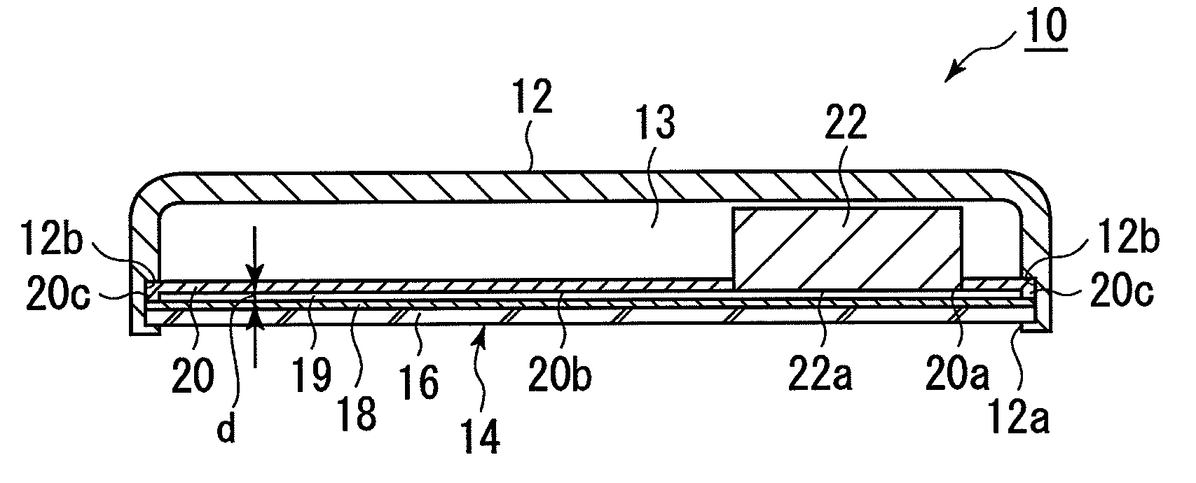
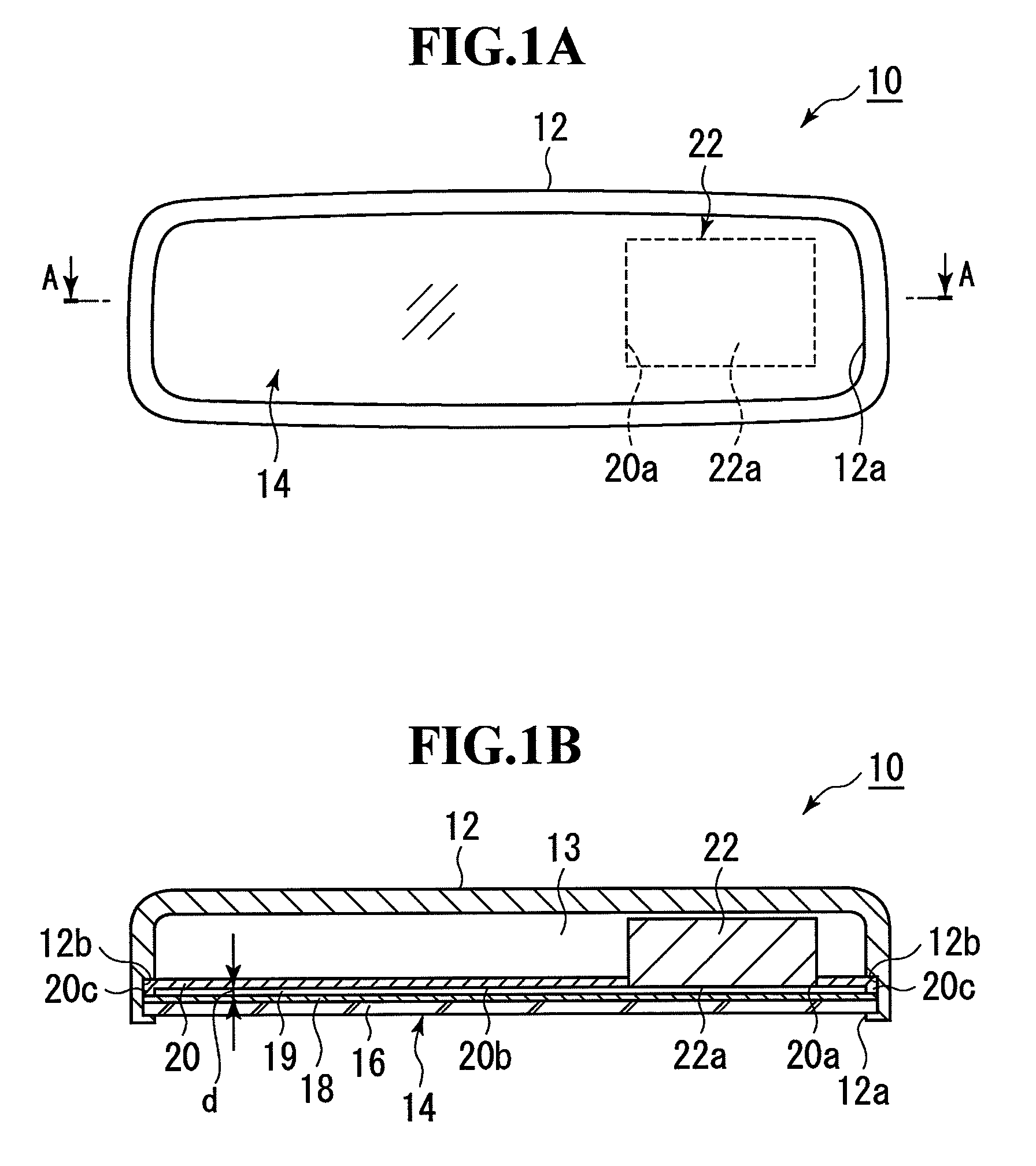
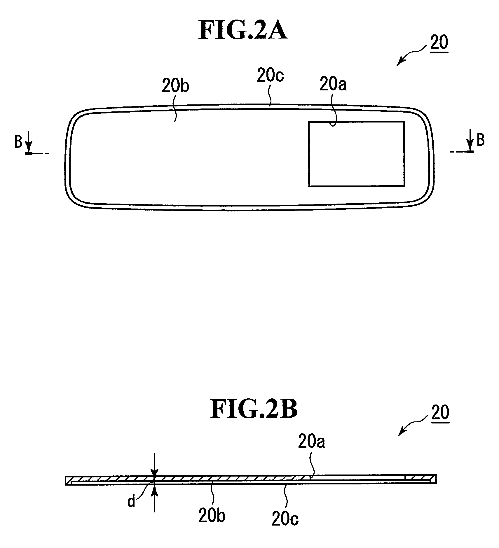
[0020]Embodiment 1 of the present invention will be described. FIG. 1 illustrates an overview of the inner structure of a vehicle inner mirror to which the present invention has been applied. FIG. 1A is a front view, and FIG. 1B is a cross-sectional view taken along a line indicated by arrows A-A in FIG. 1 A. An inner mirror 10 is formed by putting a mirror element 14 into a front surface opening 12a of a housing 12. The mirror element 14 is formed as a back-surface mirror having a semi-transmissive reflective film 18, which is formed of a dielectric multilayer film, on the entire back surface of a transparent substrate 16, which is formed of, e.g., transparent glass or transparent optical resin. On the back side of the mirror element 14, a dark color (for example, black) mask member 20 is arranged facing the back side of the mirror element 14 across a clearance gap 19 providing a predetermined distance d between the mirror element 14 and the dark color mask member 20. An opening 20...

embodiment 2

[0039]Although in embodiment 1 described above, a spacer is formed of the protrusion 20c integrated with the peripheral edge of the front surface 20b of the dark color mask member 20, a spacer can be formed of a member separated from the dark color mask member 20. FIG. 8 illustrates an embodiment including a spacer formed in such a manner. FIG. 8 is a cross-sectional view taken from a line corresponding to a line indicated by arrows A-A in FIG. 1A. The parts that are in common with those in FIG. 1 are provided with the same reference numerals. An inner mirror 36 has a clearance gap 19 providing a distance d between the mirror element 14 and the dark color mask member 20 by providing a spacer 38 between the entire peripheral edges of the mirror element 14 and the dark color mask member 20. The spacer 38 is formed of, e.g., a ring-shaped, dark color (for example, black) resin member.

[0040]Although the above-described embodiments have been described in terms of the case where the prese...


PUM

PropertyMeasurementUnit
distanceaaaaaaaaaa
distanceaaaaaaaaaa
arithmetic average roughnessaaaaaaaaaa

Abstract

Interference of light is prevented from occurring in a rear-view mirror incorporating a light-emitting display device where a dark color mask member is arranged behind a mirror element. A mirror element is formed by forming a semi-transmissive reflective film on one surface of a transparent substrate. On a back surface of the mirror element, a dark color mask member is arranged. An opening a is formed in the dark color mask member Behind the mirror element, a light-emitting display device is arranged facing the opening. A protrusion forming a spacer is formed on the entire peripheral edge of a front surface of the dark color mask member. The spacer provides a clearance gap between the semi-transmissive reflective film and the dark color mask member.

Description

[0001]The disclosure of Japanese Patent Application No. JP2008-90323 filed on Mar. 31, 2008 including the specification, drawing and abstract is incorporated herein by reference in its entirety.BACKGROUND OF THE INVENTION[0002]1. Field of the Invention[0003]The present invention relates to a rear-view mirror incorporating a light-emitting display device, which prevents interference of light from occurring where a dark color mask member is arranged behind a mirror element.[0004]2. Description of the Related Art[0005]Japanese Patent Laid-Open Nos. 2000-153736 and 2000-255321 each discloses a rear-view mirror incorporating a light-emitting display device to display information.[0006]The rear-view mirror disclosed in Japanese Patent Laid-Open No. 2000-153736 is formed by: forming a semi-transmissive reflective film formed of a dielectric multilayer film on the back surface of a mirror substrate; forming a colored paint film on the region excluding a part of the entire region of the back...

Claims


Application Information

Patent Timeline
Patent Type & Authority Patents(United States)
IPC IPC(8): G02B5/08G02F1/153
CPCB60R1/00G02B5/0833G02B5/26B60R2001/1253
Inventor TAKAYANAGI, SHINYANAKAMURA, MASATOSHI
Owner MURAKAMI CORP
Why Eureka
Try Eureka