Check patentability & draft patents in minutes with Patsnap Eureka AI!

Layered low-pass filter capable of producing a plurality of attenuation poles

a low-pass filter and plurality technology, applied in the field of layers, can solve the problems of difficult to increase attenuation, increase in insertion loss in the pass band of low-pass filter, etc., and achieve the effect of increasing attenuation

Active Publication Date: 2011-07-19
TDK CORPARATION
View PDF12 Cites 6 Cited by
  • Summary
  • Abstract
  • Description
  • Claims
  • Application Information

AI Technical Summary

Benefits of technology

The layered low-pass filter effectively increases attenuation in multiple specific narrow frequency bands within the stop band by utilizing multiple attenuation poles, preventing an increase in insertion loss and allowing for adjustable pole frequencies, thus enhancing signal filtering capabilities without enlarging the filter size.

Problems solved by technology

Disadvantageously, however, this leads to an increase in insertion loss in the pass band of the low-pass filter.
In such a case, it is difficult to increase attenuation especially in the plurality of specific narrow frequency bands present in the stop band by utilizing the attenuation pole closest to the pass band.

Method used


Image

  • Layered low-pass filter capable of producing a plurality of attenuation poles
  • Layered low-pass filter capable of producing a plurality of attenuation poles
  • Layered low-pass filter capable of producing a plurality of attenuation poles

Examples


Embodiment Construction

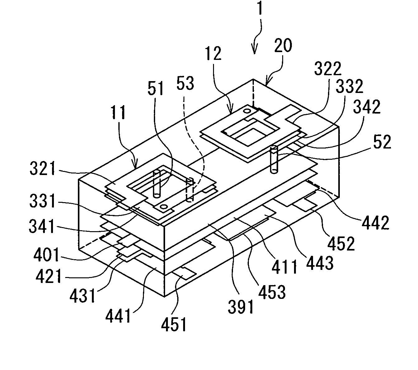
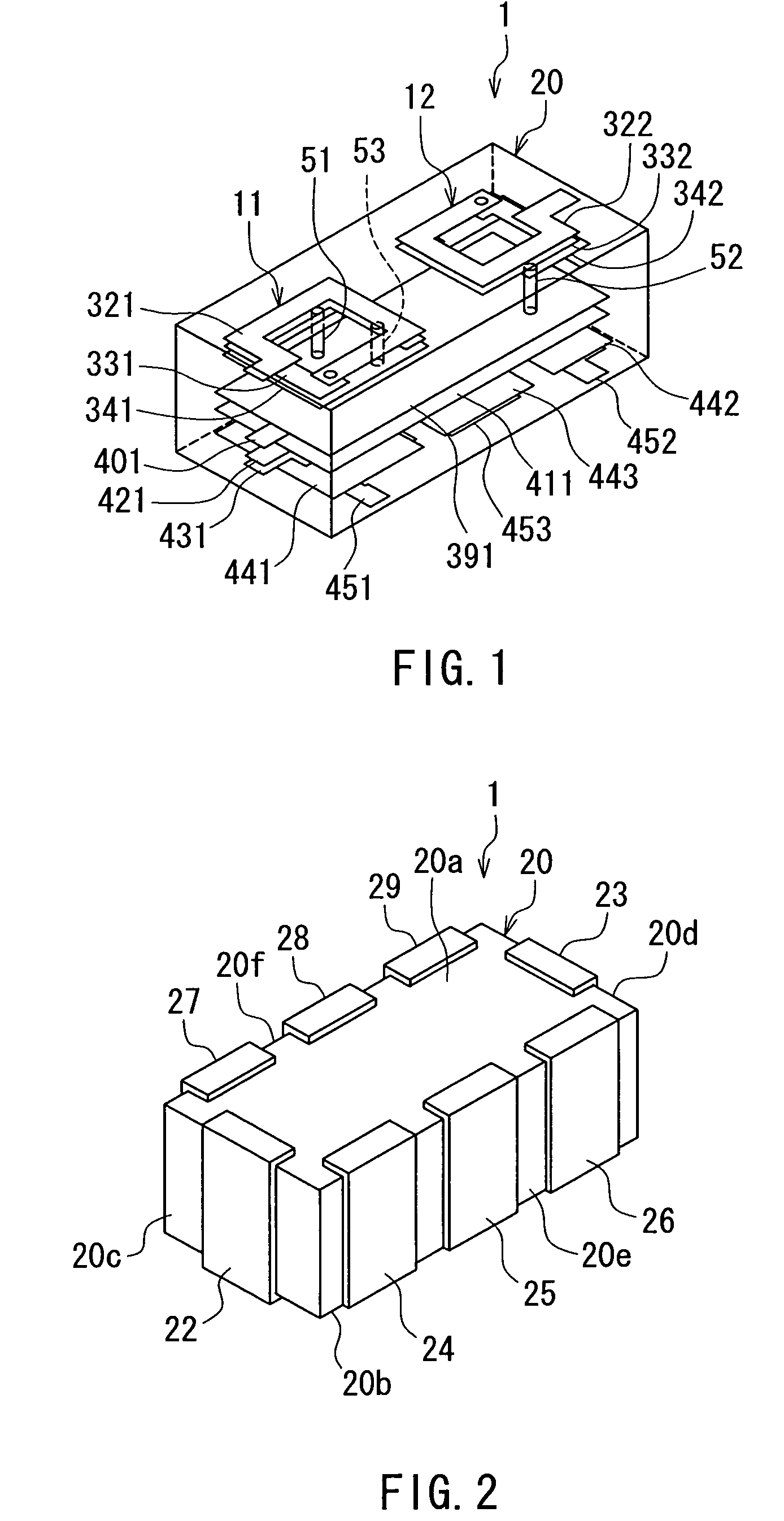
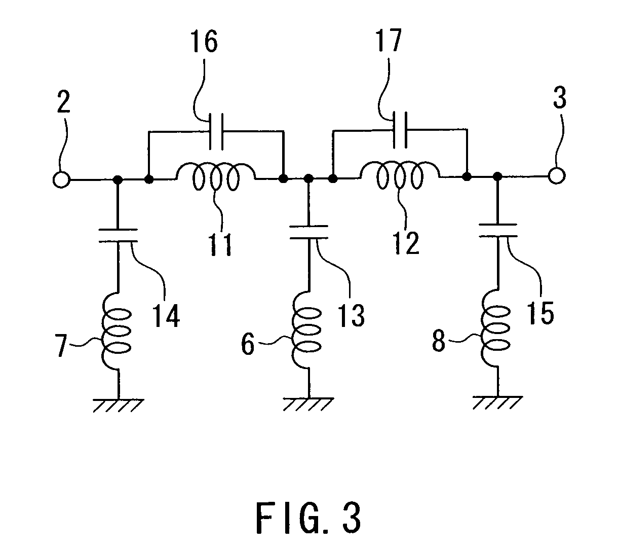
[0028]A preferred embodiment of the present invention will now be described in detail with reference to the drawings. Reference is first made to FIG. 3 to describe the circuit configuration of a layered low-pass filter according to the preferred embodiment of the invention. As illustrated in FIG. 3, the layered low-pass filter 1 according to the embodiment includes: an input terminal 2 for receiving signals; an output terminal 3 for outputting signals; five inductors 6, 7, 8, 11 and 12; and five capacitors 13 to 17.

[0029]The inductors 11 and 12 are connected in series to each other and, in terms of circuit configuration, located between the input terminal 2 and the output terminal 3. In terms of circuit configuration, the inductor 11 is located closer to the input terminal 2 than is the inductor 12. The inductor 11 corresponds to the first inductor of the present invention, and the inductor 12 corresponds to the second inductor of the present invention. Each of the inductors 11 and ...


PUM


Abstract

A layered low-pass filter includes: a first inductor and a second inductor that are connected in series and are located between an input terminal and an output terminal; a first capacitor connected in parallel to the first inductor; a second capacitor connected in parallel to the second inductor; and third to fifth capacitors and third to fifth inductors. The output of the first inductor and the input of the second inductor are connected to the ground via the third capacitor and the third inductor connected in series. The input of the first inductor is connected to the ground via the fourth capacitor and the fourth inductor connected in series. The output of the second inductor is connected to the ground via the fifth capacitor and the fifth inductor 8 connected in series.

Description

BACKGROUND OF THE INVENTION[0001]1. Field of the Invention[0002]The present invention relates to a layered low-pass filter formed using a layered substrate.[0003]2. Description of the Related Art[0004]Recently, there have been strong demands for reductions in size and thickness of electronic apparatuses for portable use typified by cellular phones and notebook personal computers, and accordingly, reductions in size and thickness have also been required for electronic components for use in such electronic apparatuses. Low-pass filters are one of the electronic components for use in such electronic apparatuses. Reductions in size and thickness are also required for low-pass filters. To meet this, it has been proposed to form a low-pass filter using a layered substrate, as disclosed in, for example, JP-A-5-259703, JP-A-5-299962, JP-A-6-097701 and JP-A-2000-101378. A low-pass filter formed using a layered substrate as mentioned above will be hereinafter called a layered low-pass filter....

Claims


Application Information

Patent Timeline
Patent Type & Authority Patents(United States)
IPC IPC(8): H03H7/00
CPCH03H7/0115H03H7/1725H03H7/1758H03H7/1766H03H2001/0085
Inventor SAKISAKA, YASUNORIKAGAYA, YUKITOSHI
Owner TDK CORPARATION
Features
  • R&D
  • Intellectual Property
  • Life Sciences
  • Materials
  • Tech Scout
  • Unparalleled Data Quality
  • Higher Quality Content
  • 60% Fewer Hallucinations
Learn More