
Attachment system with a removable and replaceable tongue for use with a reciprocating driver

a technology of reciprocating driver and attachment system, which is applied in the field of power tools, can solve the problems of significant time and inconvenience, damage or other deformation of the adapter constructed to interface with a functional tool, and the end of the adapter that interfaces with the power unit may become damaged or unusable,

Active Publication Date: 2011-07-26
ROCKY MOUNTAIN TWIST CORP
View PDF28 Cites 13 Cited by
  • Summary
  • Abstract
  • Description
  • Claims
  • Application Information

AI Technical Summary

Benefits of technology

"The present invention relates to a system for quickly and easily securing different tools to a hand-held power unit with a reciprocating output. The system includes an attachment mount and a removable and replaceable mounting member that interfaces with the power unit. This allows for quick and easy engagement and disengagement of different tools without the need for full replacement of the attachment. The system also includes an adapter that allows for the secure attachment of a functional tool to the power unit without damaging the attachment mount. The functional tool is engaged with the attachment mount using a push-on force, eliminating the need for tools. The invention provides a more convenient and efficient way to use different tools with a hand-held power unit."

Problems solved by technology

This entails a significant amount of time and inconvenience, and requires an operator to always have a tool such as alien wrench or screwdriver at the ready when it is desired to change tools to adapt the power unit for a different function.
Notwithstanding the advancements presented in U.S. Pat. No. 6,755,424, the present inventor has discovered that the reciprocating output of the power unit may damage or otherwise degrade the adapter constructed to interface with a functional tool.
In particular, the end of the adapter that interfaces with the power unit may become damaged or unusable even though the end of the adapter that receives the functional tool remains usable.

Method used


Image

  • Attachment system with a removable and replaceable tongue for use with a reciprocating driver
  • Attachment system with a removable and replaceable tongue for use with a reciprocating driver
  • Attachment system with a removable and replaceable tongue for use with a reciprocating driver

Examples


Embodiment Construction

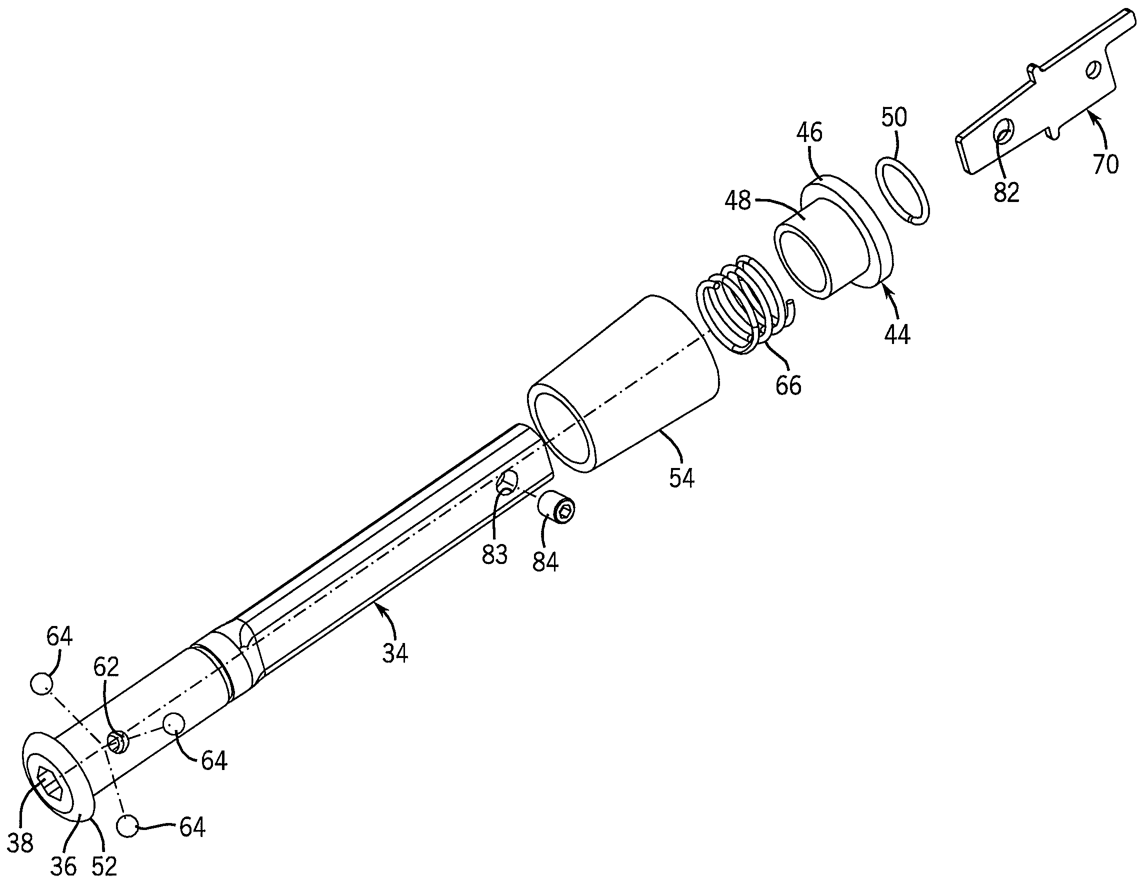
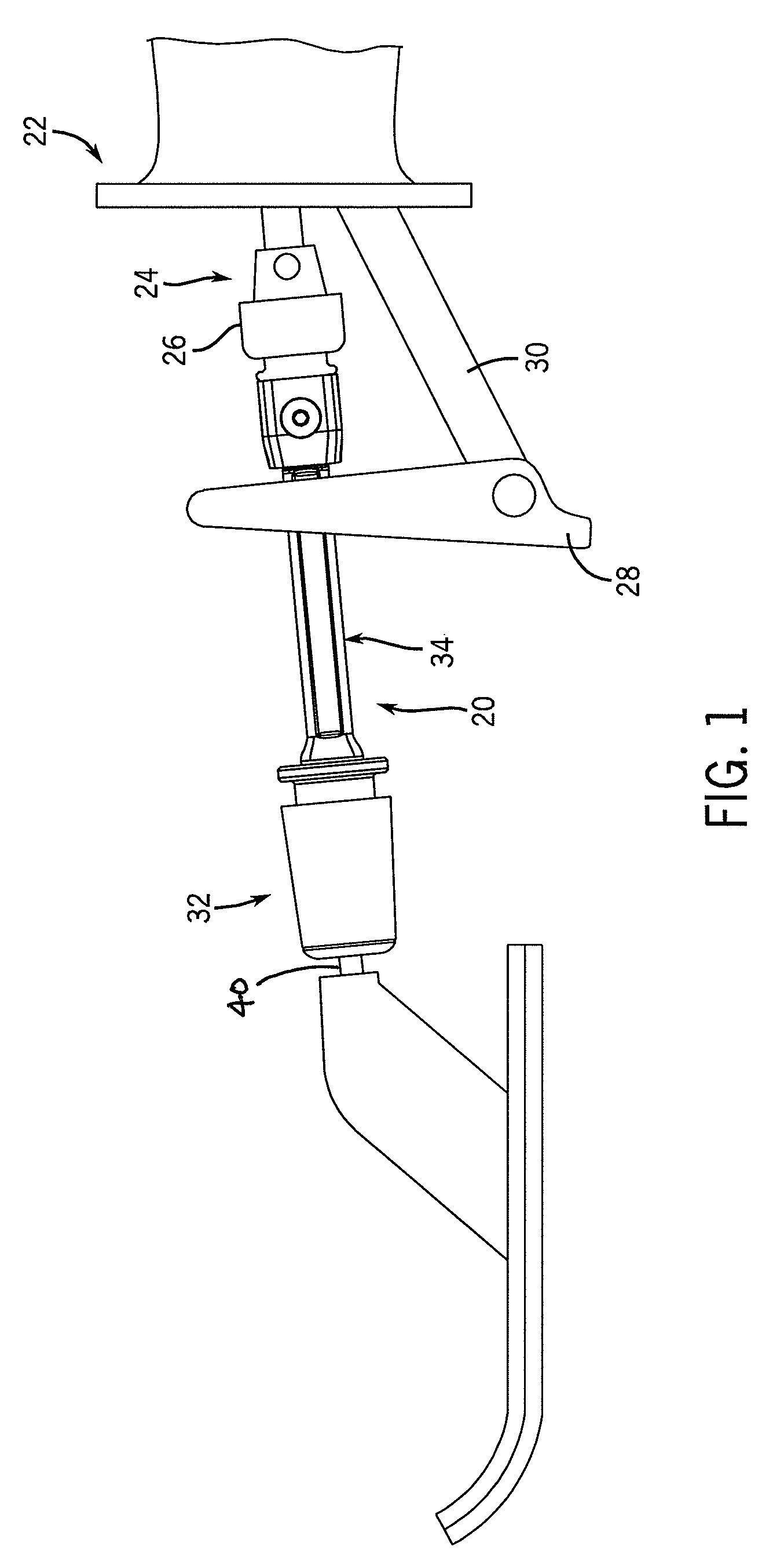
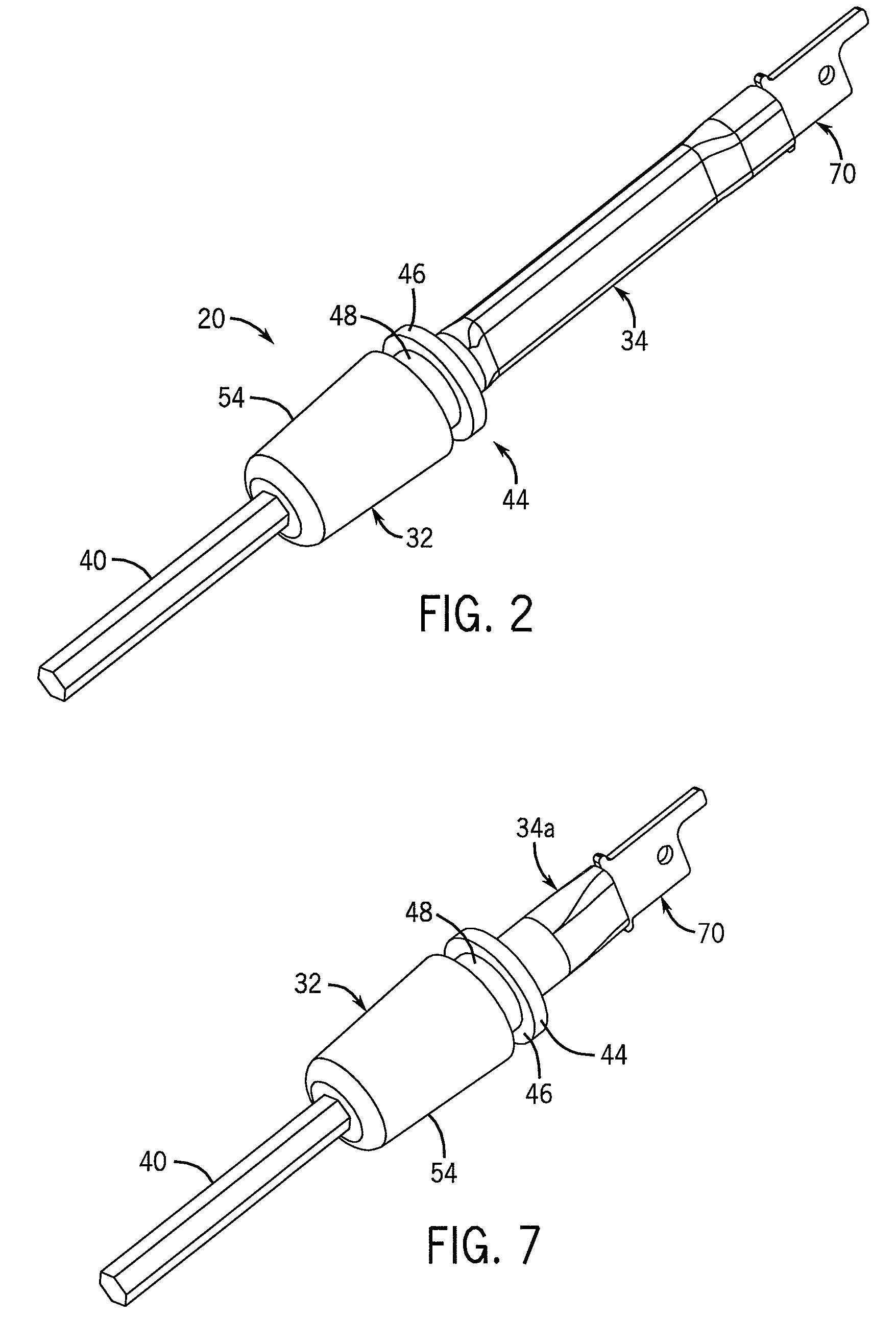
[0023]Referring now to FIG. 1, a quick change tool attachment 20 is adapted for use in connecting a tool or attachment, such as a sanding shoe, to a driver, such as a reciprocating saw. A representative driver may a reciprocating driver such as is available from Milwaukee Electric Tool under its designation SAWZALL. The end of the driver is shown at 22, and includes a tool connection area 24. In accordance with known construction, tool connection area 24 includes an outwardly facing slot within which the end of a tool or attachment is adapted to be received. Tool connection area 24 also includes a lever 26 that operates a clamp-type tool engagement mechanism for securely retaining the tool or attachment within the slot in tool connection area 24. Driver 22 may also include a shoe 28 spaced outwardly from tool connection area 24 and secured to the driver end 22 via a bracket 30.

[0024]Quick change tool attachment 20 is configured for engagement with tool connection area 24 of the reci...


PUM

PropertyMeasurementUnit
areaaaaaaaaaaa
lengthaaaaaaaaaa
biasing forceaaaaaaaaaa

Abstract

A system for use in securing an attachment to a driver having an attachment mounting area includes an attachment mount configured for releasable engagement with an attachment as well as a driver mount interconnected with the attachment mount. The driver mount includes a removable mounting member configured for engagement with the attachment mounting area of the driver.

Description

CROSS-REFERENCE TO RELATED APPLICATION[0001]This application claims the benefit of U.S. provisional application 60 / 804,047, filed Jun. 6, 2006, the disclosure of which is incorporated herein by reference.BACKGROUND AND SUMMARY OF THE INVENTION[0002]This invention relates to power tools, and more particularly to a quick-change system for releasably securing a tool to a reciprocating driver or power unit.[0003]A reciprocating power saw typically includes a hand-held power unit or driver which is operable to impart reciprocating motion to a blade attachment arrangement. A conventional saw blade for a reciprocating power saw of this type has a flat inner end formed with a tang and an aperture, which is adapted to be clamped to the blade attachment arrangement to securely retain the blade in place. In this manner, reciprocating motion is imparted to the blade in response to operation of the power unit. The clamp-type blade attachment member requires use of a tool, such as a screwdriver o...

Claims


Application Information

Patent Timeline
Patent Type & Authority Patents(United States)
IPC IPC(8): B23B31/22
CPCB23B31/1071B23D51/10Y10T279/3418Y10S279/905Y10T279/17863Y10T279/3406Y10T279/3412Y10T279/35Y10T279/17923Y10T279/17752Y10T279/17145
Inventor PAULSEN, SCOTT A.
Owner ROCKY MOUNTAIN TWIST CORP
Learn More