Fixed head clipper and disposable blade assembly

a blade assembly and fixed head technology, applied in the direction of metal working devices, etc., can solve the problems of short side portions b>24/b> relative to the blade assembly, and difficult to properly engage the blade assembly on the handle, etc., to achieve quick and easy engagement, easy to eject, and easy to engag

Inactive Publication Date: 2005-05-03
WAHL CLIPPER
View PDF10 Cites 40 Cited by
  • Summary
  • Abstract
  • Description
  • Claims
  • Application Information

AI Technical Summary

Benefits of technology

[0011]Accordingly, the present invention provides a hair clipper having a detachable and disposable blade assembly which is fixed relative to a handle portion of the clipper while in use, is readily engaged upon the handle portion for quick and easy engagement, and has a pop-off tab feature which permits the used blade assembly to be easily ejected from the handle portion with one hand without the operator touching the blades. Additionally, the large surface area of the contacting surface of the blade assembly housing facilitates accurate control over the unit's cutting angle, whether applied against the skin or against a hair comb.

Problems solved by technology

The razor, however, can cause undesirable nicks which, when occurring during pre-operative shaving, may contribute to post-operative infections.
One disadvantage of this conventional clipper unit 10 is the difficulty in properly engaging the blade assembly on the handle so that a drive member 32, normally a rotating eccentric cam member or reciprocating drive finger, will properly engage a cam follower (not shown) in the reciprocating blade 20 of the blade assembly 14.
Such units require the user to often perform relatively complicated multiple alignment and engagement steps to properly mount the blade assembly 14, which can be a frustrating and time consuming procedure.
Another disadvantage of this conventional surgical clipper 10 is that the side portions 24 are very short relative to the blade assembly 14.
Even when not in operation, upon such contact, the sharp blade teeth may puncture or rupture a thin surgical glove typically worn by a technician performing surgical procedures, thus ruining the sterile environment created by the glove, and possibly infecting the technician with potentially infectious material which may be transmitted by the patient.
This potential for infection becomes even greater if the sharp teeth. break the skin of the technician's fingers.
Additionally, where a sterile environment is required, the blade assembly must be discarded and replaced before use when the blades contact the technician's skin, which can lead to increased cost from wasted blade assemblies.
Still another disadvantage of this clipper 10 is the significant size of the opening 26 of the handle / drive system 12 which engages the housing side portions 24 of the blade assembly 14.
The larger the size of the handle 12 though, the more cumbersome the clipper 10 becomes, and the more difficult it becomes to maneuver the blade assembly 14 to shave recessed or contoured portions of the body.
This clipper configuration also has the disadvantage, described above, of requiring two hands for assembly and detachment.
The similar low profile of its housing and sliding engagement features, also require the technician to push the blade assembly onto the handle from the direction of the blades, often bringing the technician's fingers in direct contact with, and / or pressure from, the sharp blade teeth which, as noted above, can lead to undesirable consequences.

Method used


Image

  • Fixed head clipper and disposable blade assembly
  • Fixed head clipper and disposable blade assembly
  • Fixed head clipper and disposable blade assembly

Examples


Embodiment Construction

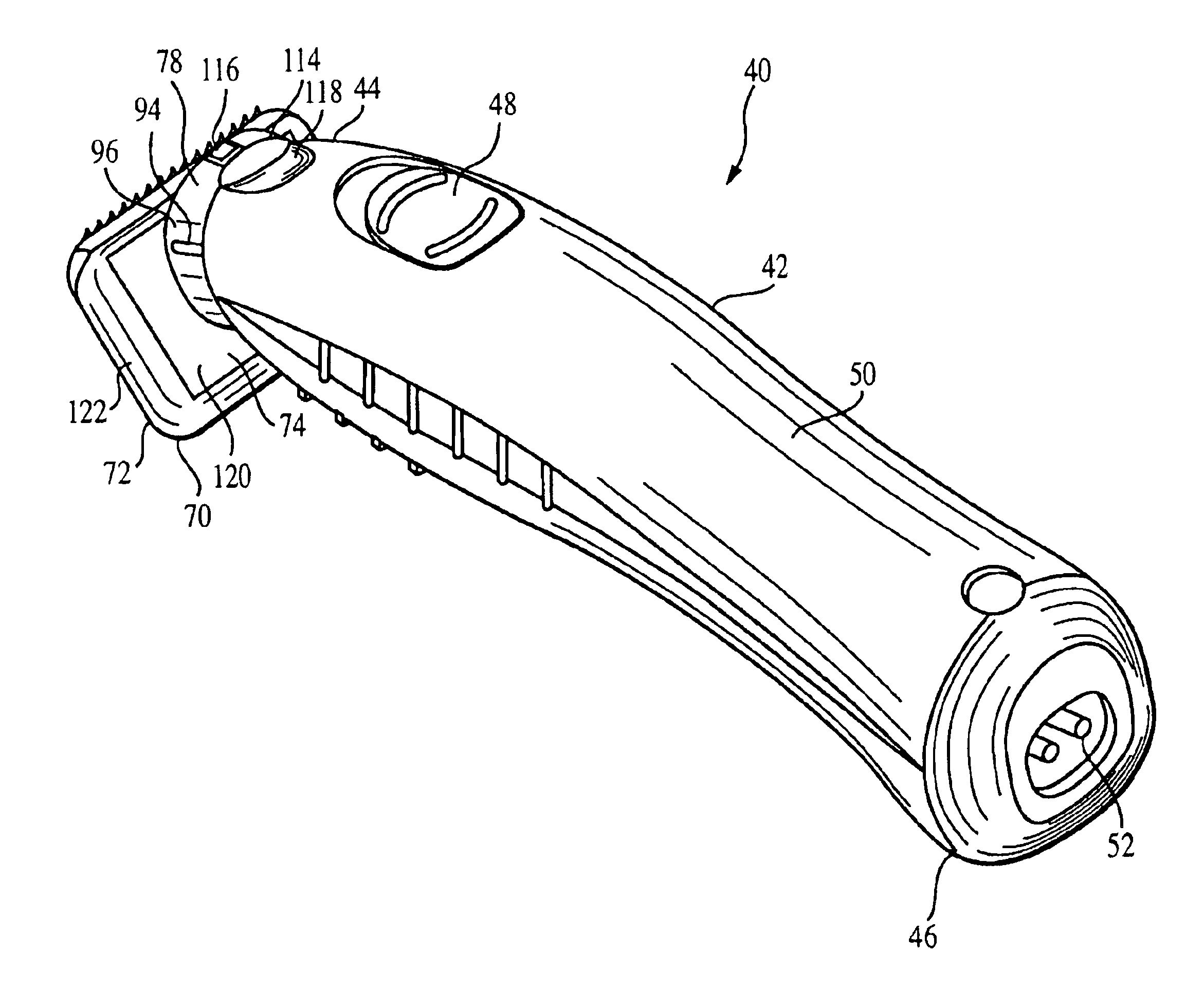
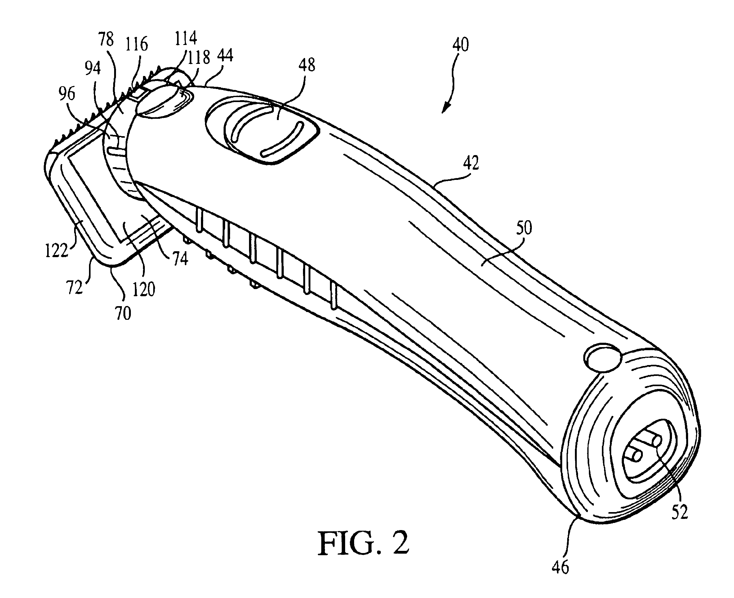
[0021]Referring now to FIGS. 2, 5 and 7, an electric hair clipper of the type suitable for use in the present invention is generally designated 40, and includes a motorized handle portion 42 having a drive end 44, a recharge end 46 opposite the drive end 44, and a switch 48 located therebetween. More specifically, the handle portion 42 includes a housing 50 preferably made of durable, impact-resistant molded polymeric or plastic material as is known in the art.

[0022]Enclosed by the housing 50 is a power source (not shown) which, in the preferred embodiment, is one or more rechargeable batteries, however disposable batteries, or an electric transformer with a power cord connected to an electrical wall outlet, are also contemplated. In the preferred embodiment, terminals 52 for engaging a recharger (not shown) are located at the recharge end 46.

[0023]As can best be seen in FIG. 5, connected to the power source in a known manner is an electric motor 54 which is secured within the housi...


PUM


Abstract

A hair clipper includes a handle portion having a drive end with a first coupler formation, and a blade assembly. The blade assembly includes a housing at least partially enclosing a reciprocating blade and a fixed blade, and having a top, bottom, and at least two sides joining the top and bottom. Integrally joined to and extending away from the bottom of the housing is a second coupler formation for engaging the first coupler formation. The first and second coupler formations form a releasable connection which inhibits movement of the blade assembly with respect to the handle portion when the two coupler formations are engaged.

Description

BACKGROUND OF THE INVENTION[0001]The present invention relates to electric hair clippers, trimmers, and shavers, and more specifically to such devices having fixed blade assemblies which are stationary in use, but detachable relative to the clipper handle.[0002]Disposable manual razors and electric clippers are conventionally used to cut and clip hair for home use, and for the removal of a patient's hair prior to surgery. The razor has a sanitary advantage of being completely disposable, while providing generally stubble-free skin after use. The razor, however, can cause undesirable nicks which, when occurring during pre-operative shaving, may contribute to post-operative infections. Electric clippers are often preferred, therefore, for surgical use. The electric clippers can quickly clear an operation site of a majority of unwanted hair to improve visibility, and without exposure to infections.[0003]FIG. 1 illustrates a conventionally available electric clipper 10. The clipper incl...

Claims


Application Information

Patent Timeline
Patent Type & Authority Patents(United States)
IPC IPC(8): B26B19/04B26B19/06
CPCB26B19/06
Inventor FREAS, JONLONG, JASON
Owner WAHL CLIPPER
Why Eureka
Try Eureka