Fuel injector

a fuel injector and injector technology, applied in the direction of fuel injectors, liquid fuel feeders, machines/engines, etc., can solve the problems of complex production and therefore high cost, and achieve the effect of minimizing the structural volume of the injector

Inactive Publication Date: 2011-08-02
ROBERT BOSCH GMBH
View PDF12 Cites 6 Cited by
  • Summary
  • Abstract
  • Description
  • Claims
  • Application Information

AI Technical Summary

Benefits of technology

[0007]The invention is based on the concept of disposing the control valve seat element, which in the prior art is stationary, movably relative to the adjustment axis, which in particular is axial, of the control valve element. As a result, the control valve seat element can orient itself relative to the sleevelike control valve element, and as a result, depending on the degree of freedom of motion of the control valve seat element, any coaxial and / or angular errors that may exist between the control valve seat element and the control valve element can be compensated for. Because of the possibility of automatic orientation of the control valve seat element relative to the adjustment axis of the control valve element, the demands for precision of the sealing face and of the control valve seat are minimized without requiring sacrifices in terms of function. All in all, as a result, an especially robust fuel injector that can be produced economically is obtained.
[0008]An embodiment of the control valve or control valve element, embodied preferably as a 2 / 2-way valve, in which the control valve or control valve element is pressure-balanced in the axial direction in its closing position is especially advantageous. This can be achieved in a sleevelike control valve element in a simple way by providing that the diameter of the sealing line with which the control valve seat element rests on the control valve seat corresponds to the axially spaced-apart, inner guide diameter of the control valve element. This kind of embodiment of the fuel injector is especially suitable for use at rail pressures on the far side of 1800 bar. The attainment of an axial pressure equilibrium therefore makes it possible to use smaller (less-powerful) and in particular electromagnetic actuators and control closing springs. To minimize the danger of bouncing upon closure of the control valve element, an embodiment can also be attained in which the control valve element is pressure-balanced in the axial direction not completely but only approximately. Preferably, a pressure stage acting in the closing direction of the control valve seat element is attained then. To that end, the inner guide diameter of the control valve element should merely be selected as somewhat greater than the diameter of the sealing line.
[0010]An embodiment of the fuel injector can be obtained in which the control valve seat element is braced, preferably in the axial direction, on a component which is disposed stationary relative to the adjustment axis of the control valve element. As a result, in an especially simple and effective way, a disposition of the control valve seat element that is displaceable relative to the adjustment axis can be achieved. An embodiment in which the control valve seat element is retained on the component solely by the fuel pressure inside the fuel injector, or in other words is acted upon counter to the component by a hydraulic force, is especially advantageous.
[0012]To attain especially great sturdiness of the fuel injector, particularly with regard to particles located in the fuel, an embodiment is preferred in which the control valve seat element has at least one partly spherical portion or is embodied entirely as a ball. In an embodiment in which the control valve seat element has at least one partly spherical portion, the partly spherical portion can be oriented toward the control valve seat, and / or a partly spherical portion can serve to brace the control valve seat on a component that is either stationary relative to the adjustment axis of the control valve element or is movable, preferably displaceable, relative to this adjustment axis.
[0016]Especially whenever a guide extension, for attaining internal guidance for the sleevelike control valve element, is embodied on a throttle plate, an embodiment is preferred in which the adjustment axis of the control valve element is aligned axially with the adjustment axis of the injection valve element. An embodiment is also attainable in which the adjustment axis of the control valve element and the adjustment axis of the injection valve element are disposed offset from one another, transversely to the length of the adjustment axes. This kind of embodiment is suitable for minimizing the structural volume of the injector, especially whenever the bottom plate, having the guide extension for guiding the control valve seat, is embodied as a separate component by a throttle plate that has the outlet throttle restriction and / or the inlet throttle restriction for a control chamber.

Problems solved by technology

A disadvantage of the known fuel injector is that the control valve element sealing face that cooperates with the control valve seat must be ground extremely exactly and oriented extremely precisely with the control valve element seat, which makes production complicated and therefore expensive.

Method used


Image

  • Fuel injector
  • Fuel injector
  • Fuel injector

Examples


Embodiment Construction

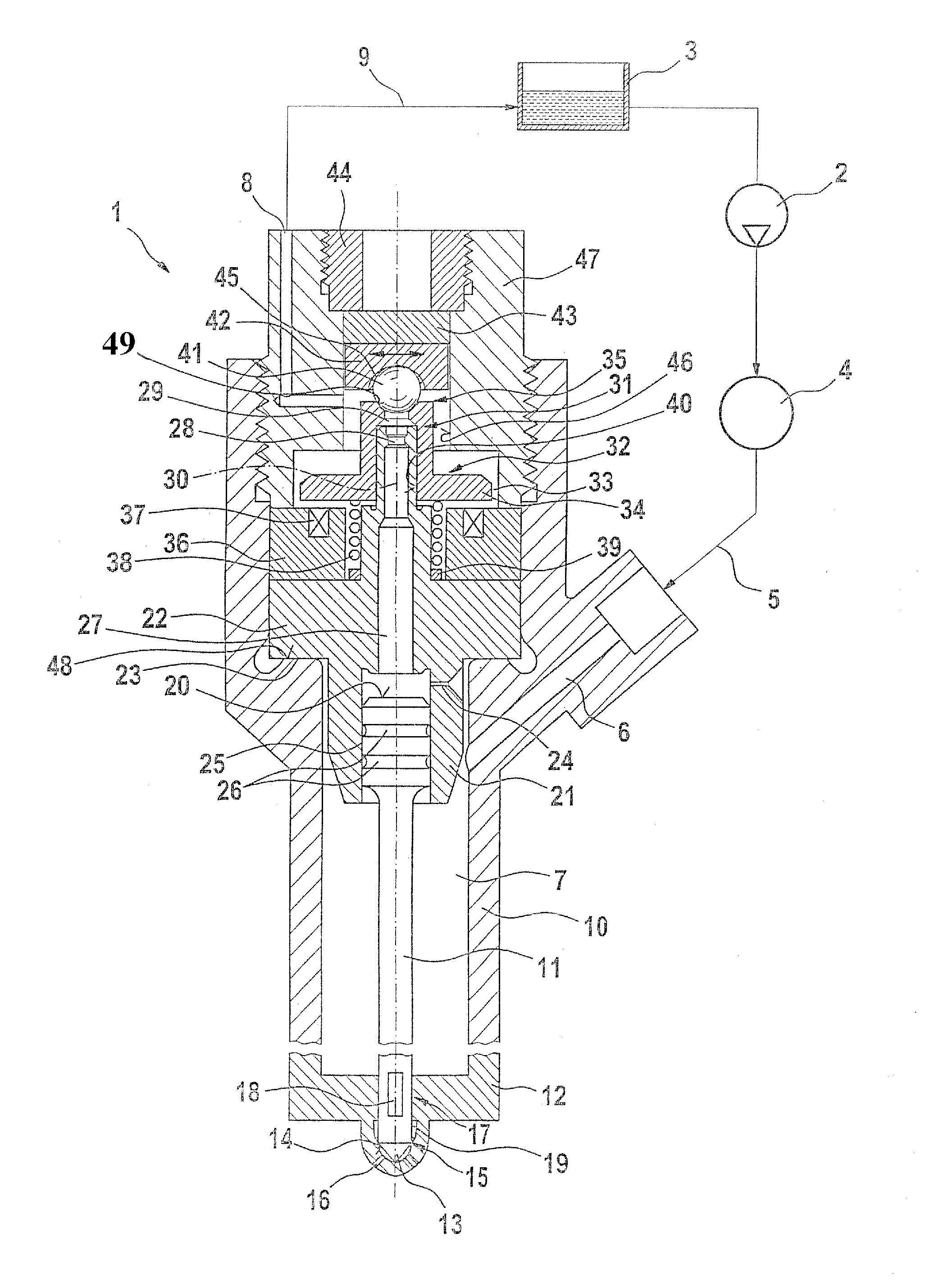
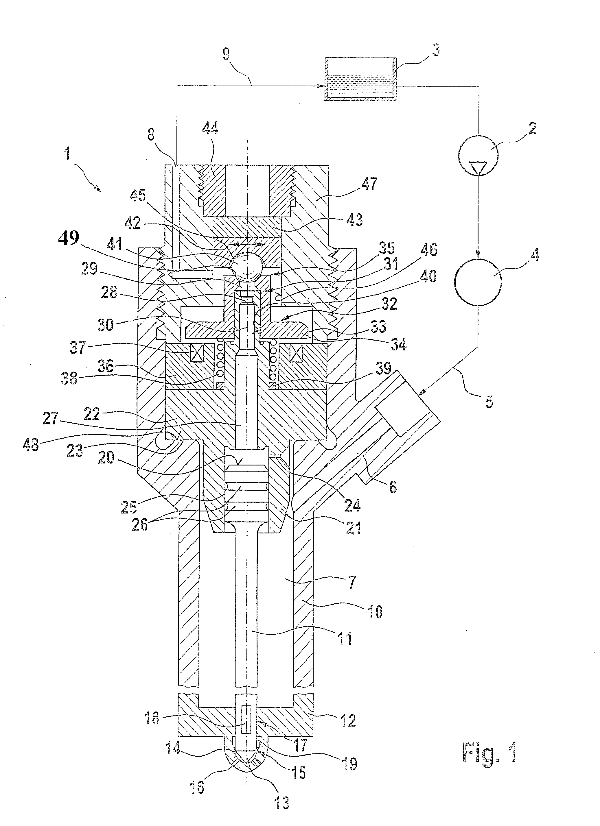
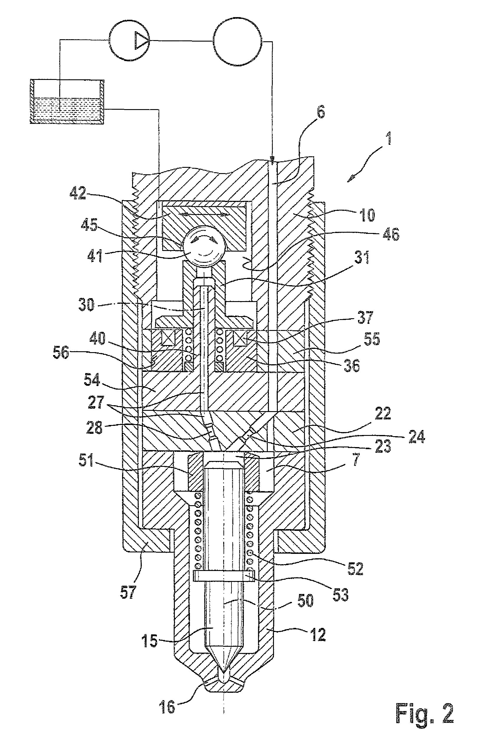
[0025]In the drawings, identical components and components having the same function are identified by the same reference numerals.

[0026]In FIG. 1, a fuel injector 1 embodied as a common rail injector is show for injecting fuel into a combustion chamber, not shown, of an internal combustion engine, also not shown, of a motor vehicle. A high-pressure pump 2 supplies fuel from a tank 3 into a high-pressure fuel reservoir 4 (rail). In the rail, fuel, in particular diesel or gasoline, is stored at high pressure, which in this exemplary embodiment is approximately 2000 bar. The fuel injector 1, along with other injectors, not shown, is connected to the high-pressure fuel reservoir 4 via a supply line 5. The supply line 5 discharges into a supply conduit 6, which in turn discharges into a pressure chamber 7 (high-pressure region) of the fuel injector 1. The fuel flowing into the pressure chamber 7 flows directly into the combustion chamber of the engine in an injection event. The fuel inje...


PUM


Abstract

The invention relates to a fuel injector, in particular a common rail injector, for injecting fuel into a combustion chamber of an internal combustion engine. The fuel injector has an injection valve element which is adjustable between a closing position and an opening position and which is switchable by means of a control valve. The control valve has a sleevelike control valve element that is adjustable along an adjustment axis and in its closing position rests sealingly on a control valve seat element. According to the invention, it is provided that the control valve seat element is disposed movably relative to the adjustment axis of the control valve element.

Description

CROSS-REFERENCE TO ELATED APPLICATIONS[0001]This application is based on Germ Patent Application 10 2008 001 597.0 filed May 6, 2008, upon which priority is claimed.BACKGROUND OF THE INVENTION[0002]1. Field of the Invention[0003]The invention relates to a fuel injector, in particular a common rail injector, for injecting fuel into a combustion chamber of an internal combustion engine.[0004]2. Description of the Prior Art[0005]From European Patent Disclosure EP 1 612 403 A1, a common rail injector is known, having a control valve that is pressure-balanced in the axial direction. By means of the control valve, which has a sleevelike control valve element, the fuel pressure inside a control chamber, defined on the face end by an injection valve element, can be varied. By the variation of the fuel pressure inside the control chamber, the injection valve element is adjusted between an opening position and a closing position, and in its opening position, the injection valve element enable...

Claims


Application Information

Patent Timeline
Patent Type & Authority Patents(United States)
IPC IPC(8): F02M59/46F16K25/00
CPCF02M47/027F02M63/0042F02M63/0071F02M63/0077F02M63/008F02M63/007
Inventor EISENMENGER, NADJA
Owner ROBERT BOSCH GMBH
Why Eureka
Try Eureka