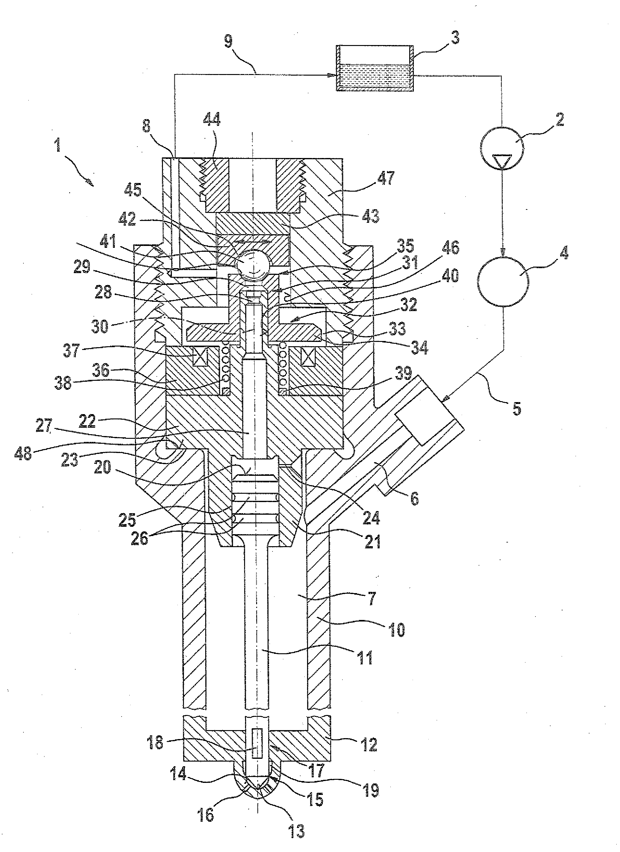
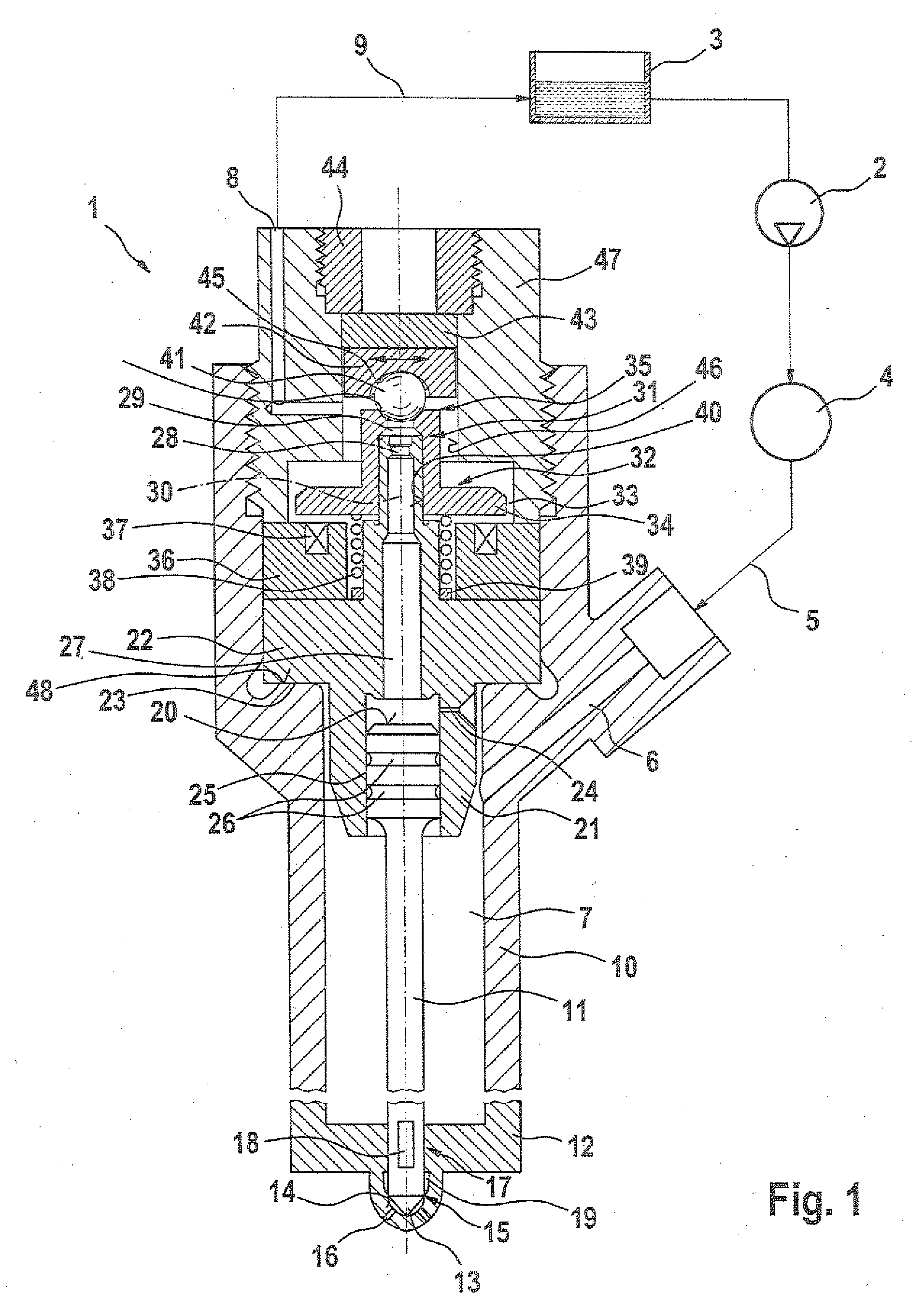
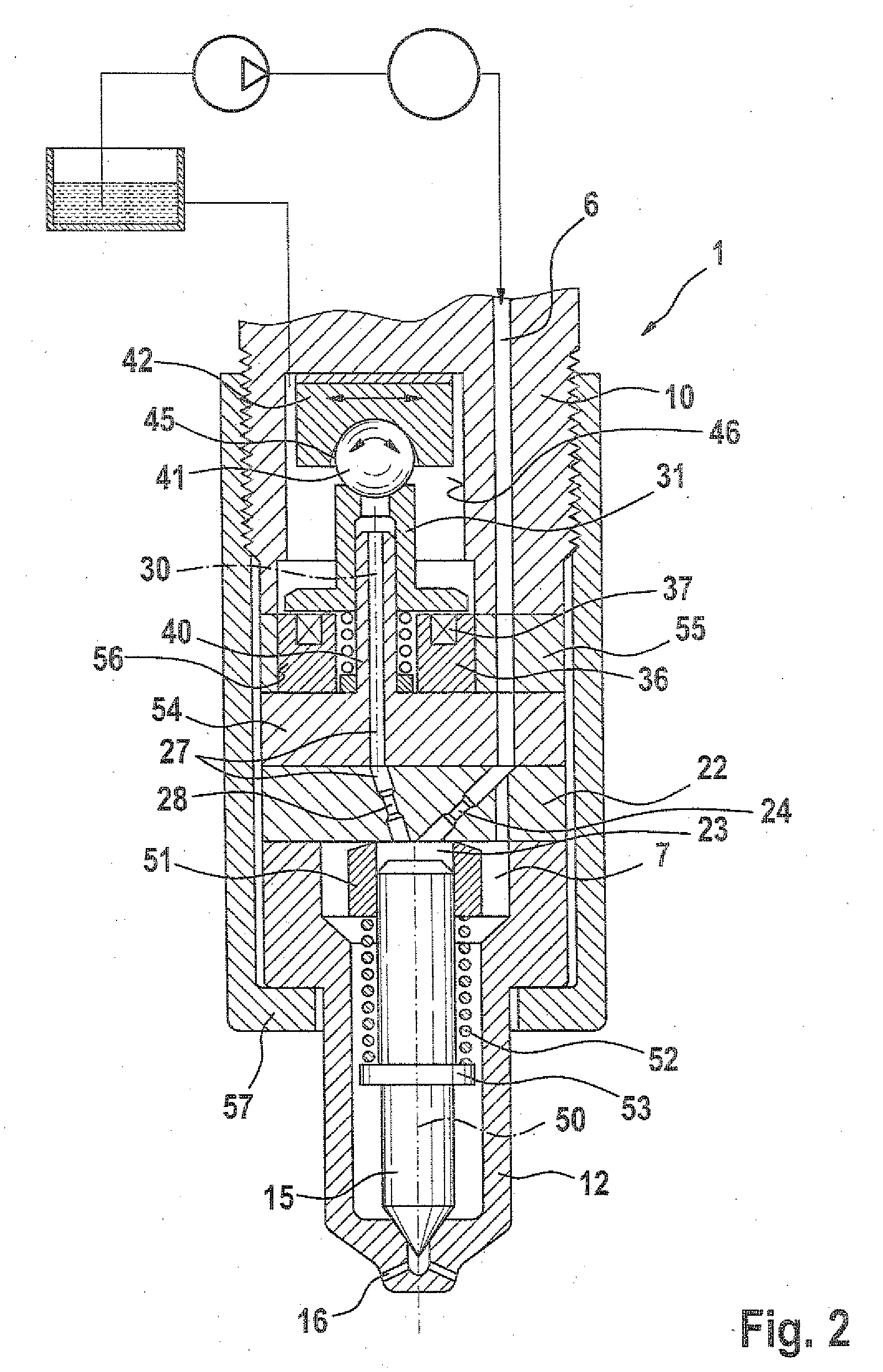
[0007]The invention is based on the concept of disposing the control valve seat element, which in the prior art is stationary, movably relative to the adjustment axis, which in particular is axial, of the control valve element. As a result, the control valve seat element can orient itself relative to the sleevelike control valve element, and as a result, depending on the degree of freedom of motion of the control valve seat element, any coaxial and / or angular errors that may exist between the control valve seat element and the control valve element can be compensated for. Because of the possibility of automatic orientation of the control valve seat element relative to the adjustment axis of the control valve element, the demands for precision of the sealing face and of the control valve seat are minimized without requiring sacrifices in terms of function. All in all, as a result, an especially robust fuel injector that can be produced economically is obtained.
[0008]An embodiment of the control valve or control valve element, embodied preferably as a 2 / 2-way valve, in which the control valve or control valve element is pressure-balanced in the axial direction in its closing position is especially advantageous. This can be achieved in a sleevelike control valve element in a simple way by providing that the
diameter of the sealing line with which the control valve seat element rests on the control valve seat corresponds to the axially spaced-apart, inner guide
diameter of the control valve element. This kind of embodiment of the fuel injector is especially suitable for use at rail pressures on the far side of 1800 bar. The attainment of an
axial pressure equilibrium therefore makes it possible to use smaller (less-powerful) and in particular electromagnetic actuators and control closing springs. To minimize the danger of bouncing upon closure of the control valve element, an embodiment can also be attained in which the control valve element is pressure-balanced in the axial direction not completely but only approximately. Preferably, a pressure stage acting in the closing direction of the control valve seat element is attained then. To that end, the inner guide
diameter of the control valve element should merely be selected as somewhat greater than the diameter of the sealing line.
[0010]An embodiment of the fuel injector can be obtained in which the control valve seat element is braced, preferably in the axial direction, on a component which is disposed stationary relative to the adjustment axis of the control valve element. As a result, in an especially simple and effective way, a disposition of the control valve seat element that is displaceable relative to the adjustment axis can be achieved. An embodiment in which the control valve seat element is retained on the component solely by the fuel pressure inside the fuel injector, or in other words is acted upon counter to the component by a hydraulic force, is especially advantageous.
[0012]To attain especially great sturdiness of the fuel injector, particularly with regard to particles located in the fuel, an embodiment is preferred in which the control valve seat element has at least one partly spherical portion or is embodied entirely as a ball. In an embodiment in which the control valve seat element has at least one partly spherical portion, the partly spherical portion can be oriented toward the control valve seat, and / or a partly spherical portion can serve to brace the control valve seat on a component that is either stationary relative to the adjustment axis of the control valve element or is movable, preferably displaceable, relative to this adjustment axis.
[0016]Especially whenever a guide extension, for attaining internal guidance for the sleevelike control valve element, is embodied on a
throttle plate, an embodiment is preferred in which the adjustment axis of the control valve element is aligned axially with the adjustment axis of the injection valve element. An embodiment is also attainable in which the adjustment axis of the control valve element and the adjustment axis of the injection valve element are disposed offset from one another, transversely to the length of the adjustment axes. This kind of embodiment is suitable for minimizing the structural volume of the injector, especially whenever the bottom plate, having the guide extension for guiding the control valve seat, is embodied as a separate component by a
throttle plate that has the outlet
throttle restriction and / or the inlet throttle restriction for a control chamber.


