
System and method for loading software into a control panel for a chiller system

a chiller system and software technology, applied in the direction of program control, lighting and heating apparatus, instruments, etc., can solve the problems of increasing the cost and complexity of the control panel, one card can be used to update only one, and the software update is expensive, so as to reduce the cost of the entire chiller system and the cost of memory devices and support components

Inactive Publication Date: 2008-10-07
JOHNSON CONTROLS TYCO IP HLDG LLP
View PDF26 Cites 8 Cited by
  • Summary
  • Abstract
  • Description
  • Claims
  • Application Information

AI Technical Summary

Benefits of technology

[0013]One advantage of the present invention is that the control program(s) stored in memory can be updated electronically without having to replace memory devices on a circuit board in the control panel.
[0014]Another advantage of the present invention is that the cost of memory devices and support components in the control panel is minimized, thereby lowering the cost of the entire chiller system.
[0015]Still another advantage of the present invention is that a control program can be loaded into a control panel without the control panel having a boot program for the control system.

Problems solved by technology

One drawback of this type of software update is that it can result in a substantial cost for the software update because of having to obtain new memory devices with the new control program.
One drawback of this technique is that the need for the intermediate controller increases the cost and the complexity of the control panel.
One disadvantage of this technique is that one card can be used to update only one system.
One disadvantage of this invention is that involves complicated circuitry to determine where to store the control software and when to initiate the copying process.

Method used


Image

  • System and method for loading software into a control panel for a chiller system
  • System and method for loading software into a control panel for a chiller system
  • System and method for loading software into a control panel for a chiller system

Examples


Embodiment Construction

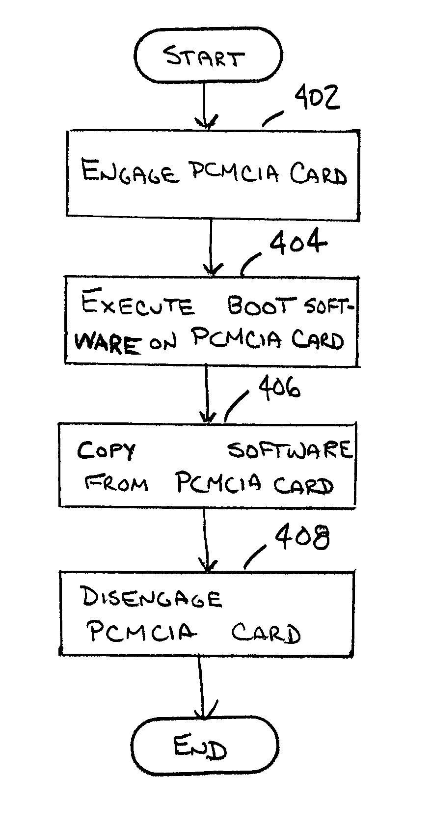
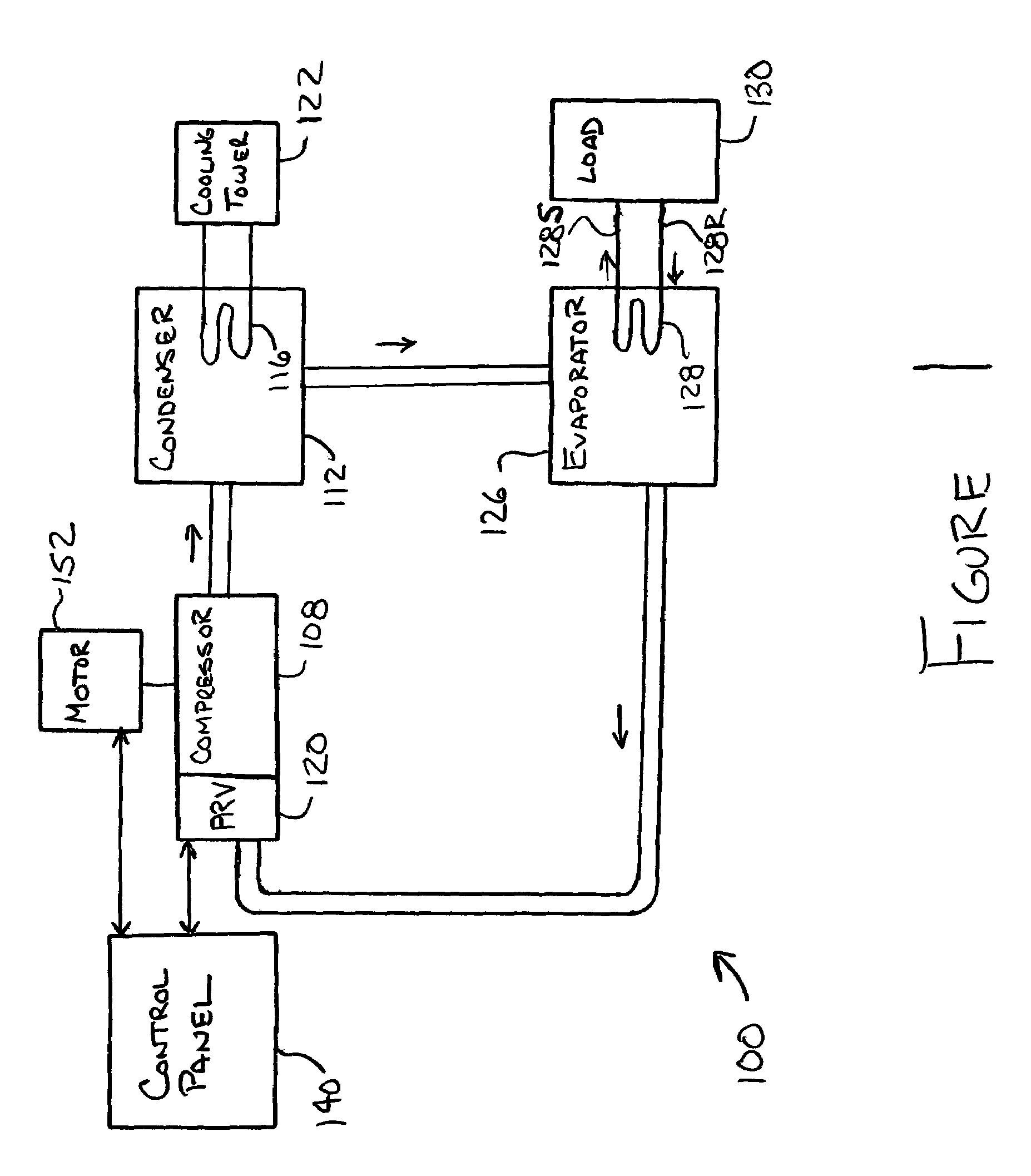
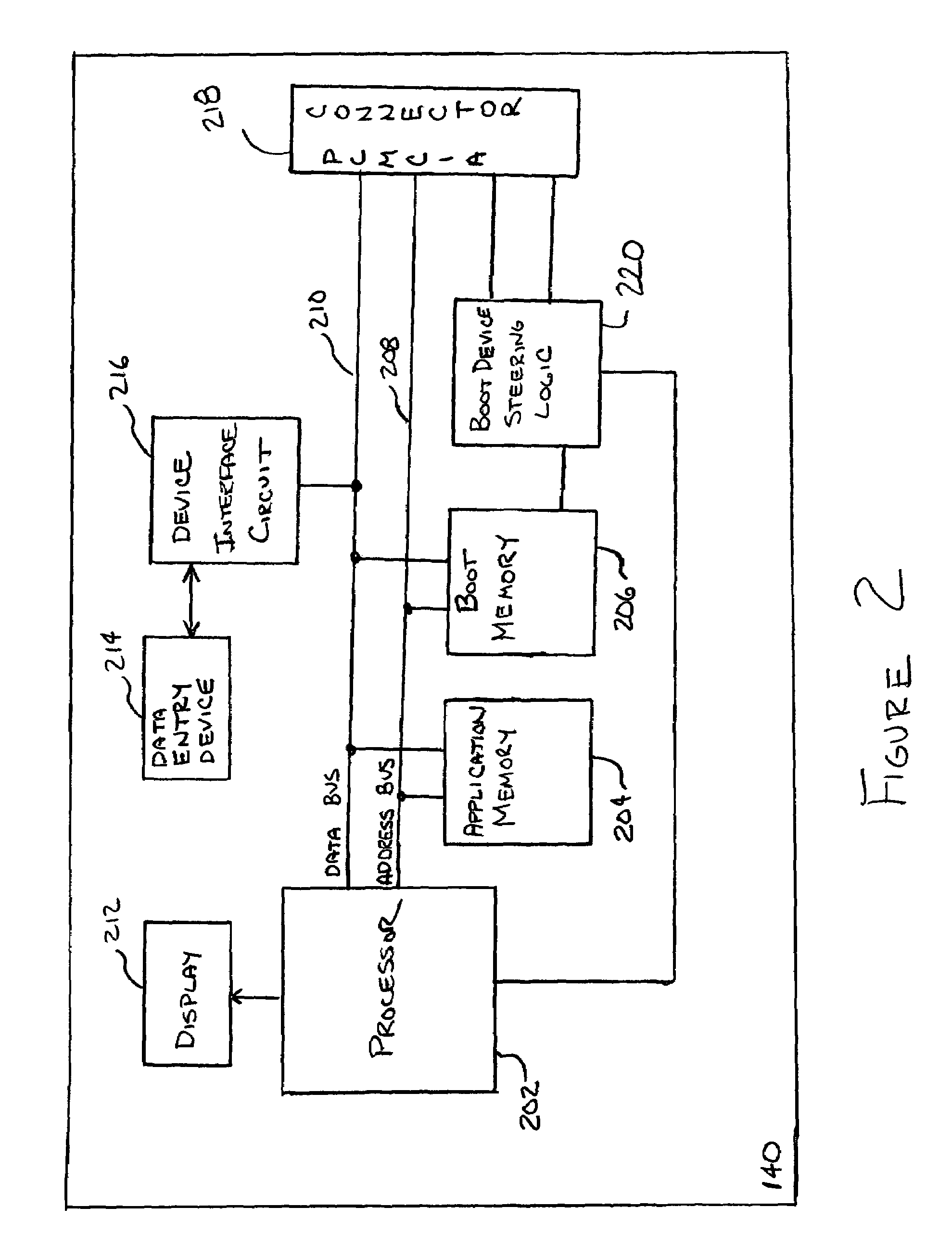
[0025]A general system to which the invention can be applied is illustrated in FIG. 1. As shown, the heating, ventilation, and air conditioning (HVAC), refrigeration or liquid chiller system 100 includes a compressor 108, a condenser 112, a water chiller or evaporator 126, and a control panel 140, which control panel 140 can be positioned locally and / or remotely to the system 100. The control panel 140 receives input signals from the system 100, e.g., temperature and pressure measurements, that indicate the performance of the system 100 and transmits signals to components of the system 100, e.g., a compressor capacity control signal, to control the operation of the system 100. The configuration of the control panel 140 and the loading of software into the control panel 140 will be discussed in greater detail below. The conventional liquid chiller system 100 includes many other features that are not shown in FIG. 1. These features have been purposely omitted to simplify the drawing f...


PUM


Abstract

A system and process for loading control software into the control panel of a liquid chiller system is provided. A PCMCIA card socket is installed on a circuit board of a liquid chiller control system and is in direct connection with microprocessor data and address buses. A linear flash PCMCIA card having new control software for the control panel is inserted into the PCMCIA card socket when the control panel is de-energized. The control software from the PCMCIA card is loaded into a flash memory of the control system by software executed directly from the PCMCIA card. The software in the PCMCIA card erases the flash memory of the control system, copies the control software from the PCMCIA card to the flash memory and then confirms that the copy of the control software was successful. After the control software has been copied, the control panel is de-energized, the PCMCIA card is removed and the chiller system is restarted and executes the new control software stored in the flash memory.

Description

CROSS-REFERENCE TO RELATED APPLICATIONS[0001]This application claims the benefit of U.S. Provisional Application No. 60 / 495,411 filed Aug. 15, 2003.BACKGROUND OF THE INVENTION[0002]The present invention relates generally to loading software into a control panel. More specifically, the present invention relates to the loading of control software into the control panel of a liquid chiller system using a linear flash PCMCIA card.[0003]The operation of a liquid chiller system can be controlled by a control software program(s) executed by a microprocessor on a control panel of the liquid chiller system. The microprocessor based control system typically includes a non-volatile memory device(s) or memory residing on a circuit board(s) in the control panel for storing the software program executed by the microprocessor during normal operation of the liquid chiller system. In microprocessor based control systems requiring only a small amount of memory for program storage, the non-volatile me...

Claims


Application Information

Patent Timeline
Patent Type & Authority Patents(United States)
IPC IPC(8): G06F11/00F25B49/00G05B19/042G06F9/445
CPCF25B49/00G05B19/0426G06F8/65G05B2219/23307G05B2219/23339G05B2219/23342G05B2219/23417G05B2219/2654G06F9/445
Inventor SMITH, BART ANDREWBOYER, JEFFREY DANIEL
Owner JOHNSON CONTROLS TYCO IP HLDG LLP
Learn More