Hammer

a technology of hammer and hammer head, which is applied in the field of hammer to achieve the effect of reducing the amount of vibration

Inactive Publication Date: 2011-08-02
BLACK & DECKER INC
View PDF23 Cites 26 Cited by
  • Summary
  • Abstract
  • Description
  • Claims
  • Application Information

AI Technical Summary

Benefits of technology

[0012]a vibration dampener which connects between the handle and the body and which reduces the amount of angular vibration transmitted from the body to the handle;
[0016]The vibration dampener can comprises biasing means, such as a spring, which connects between the handle and the body and which biases the handle towards a predetermined angular position. The biasing means damps the rotary vibration about the centre of gravity and thus reduces the amount of vibration which is transferred to the handle from the body.

Problems solved by technology

However, all types of hammer will have a hammer mechanism which, when activated, will impart impacts to a cutting tool when held in the tool holder.

Method used


Image

  • Hammer
  • Hammer
  • Hammer

Examples


Embodiment Construction

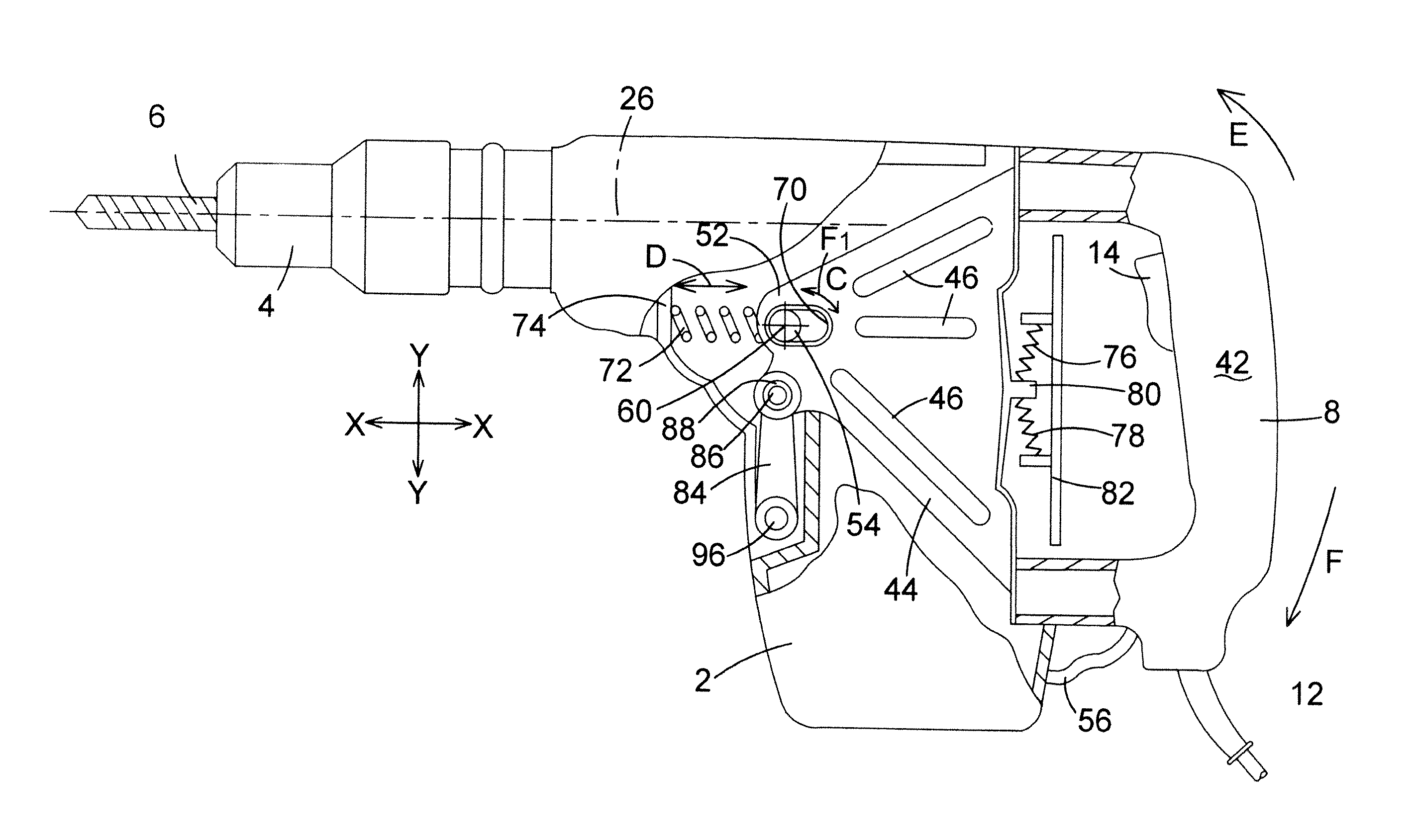
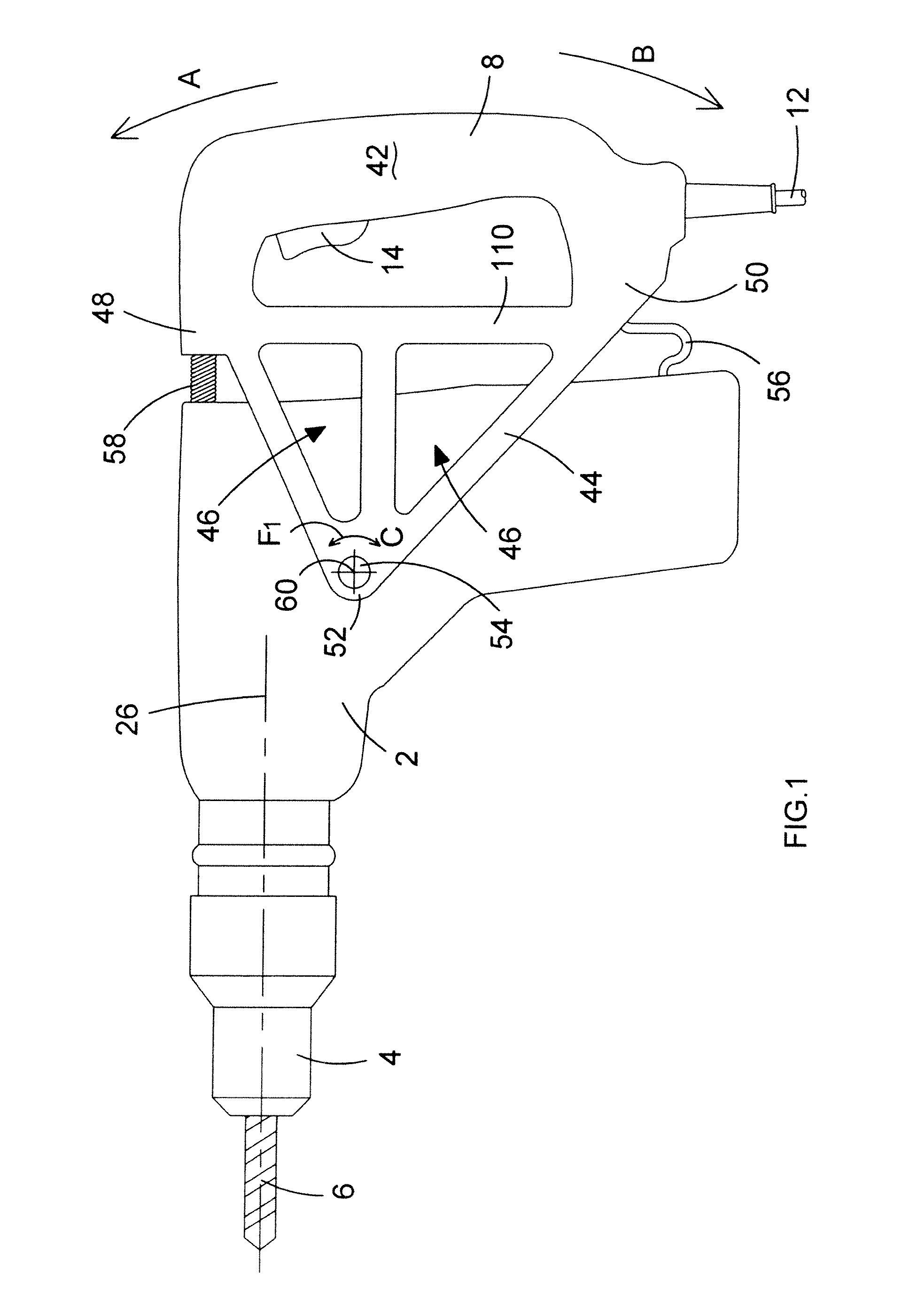
[0025]Referring to FIGS. 1, 2, and 3, the hammer comprises a body 2. Mounted on the front of the body 2 is a tool holder 4 which is capable of holding a cutting tool 6, such as a drill bit. Pivotally mounted on the body 2 is a handle 8 by which a user can support the hammer.

[0026]Mounted inside the body 2 is an electric motor 10 (see FIG. 2) which is powered via a mains electric cable 12 via a trigger switch 14. Depression of the trigger switch 14 activates the motor 10.

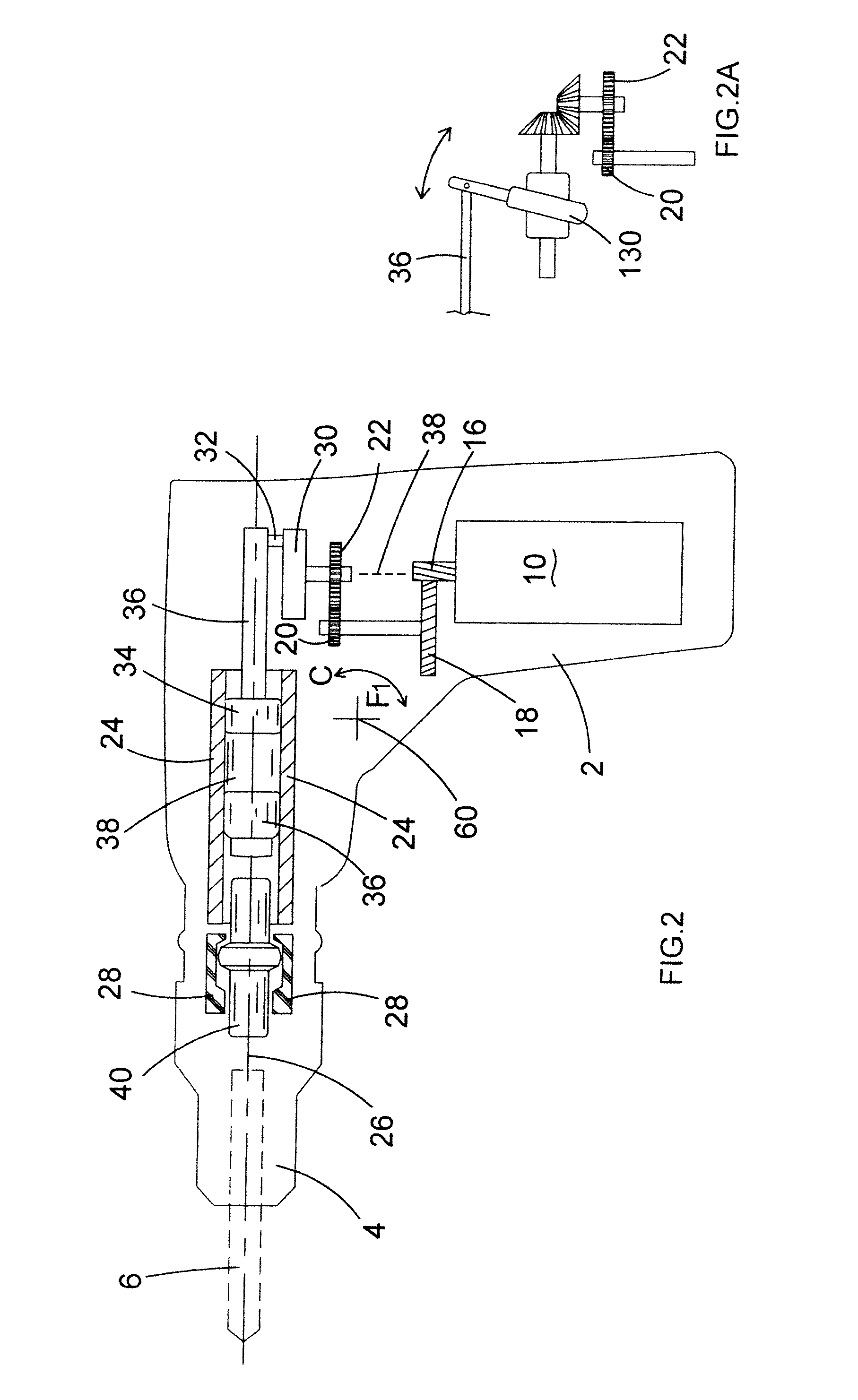
[0027]The drive spindle 16 of the motor 10 drives a hammer mechanism (which is described in more detail below) via a number of gears 18, 20, 22. A cylinder 24 of circular cross section is mounted within the body 2. The longitudinal axis 26 of the cylinder 24 is coaxial with the longitudinal axis of a cutting tool 6 when held in the tool holder 4. A beat piece support structure 28 is mounted within the body 2 between the cylinder 24 and the tool holder 4.

[0028]As shown in FIG. 2, the hammer mechanism includes a crank ...


PUM

PropertyMeasurementUnit
gravityaaaaaaaaaa
pressuresaaaaaaaaaa
rotational forcesaaaaaaaaaa

Abstract

A hammer comprising: a body; a tool holder mounted on the body for holding a cutting tool; a handle pivotally mounted on the body about an axis; a vibration dampener which connects between the handle and the body and which reduces the amount of angular vibrations transmitted from the body to the handle; a motor mounted within the body; a hammer mechanism mounted in the body, capable of being driven by the motor when the motor is activated, the hammer mechanism, when driven, imparting impacts onto a cutting tool 6 when held by the tool holder; wherein the handle is pivotally mounted about a pivot axis which passes through the centre of gravity of the hammer.

Description

CROSS-REFERENCE TO RELATED APPLICATIONS[0001]This application claims priority, under 35 U.S.C. §119(a)-(d), to UK Patent Application No. GB 08 049 63.7 filed Mar. 18, 2008, the contents of which is incorporated herein by reference in its entirety.FIELD OF THE INVENTION[0002]The present invention relates to a hammer and in particular, to a handle for a hammer.BACKGROUND OF THE INVENTION[0003]One type of hammer, often referred to as a hammer drill, can have three modes of operation. Such a hammer typically comprises a spindle mounted for rotation within a housing which can be selectively driven by a rotary drive arrangement within the housing. The rotary drive arrangement is driven by a motor also located within the housing. The spindle rotatingly drives a tool holder of the hammer drill which in turn rotatingly drives a cutting tool, such as a drill bit, releasably secured within it. Within the spindle is generally mounted a piston which can be reciprocatingly driven by a hammer driv...

Claims


Application Information

Patent Timeline
Patent Type & Authority Patents(United States)
IPC IPC(8): B25D17/04
CPCB25D17/043B25D2250/245B25D2250/371
Inventor HAHN, NORBERT
Owner BLACK & DECKER INC
Why Eureka
Try Eureka