Body cavity irrigation device

a body cavity and irrigation device technology, applied in the field of devices, can solve the problems of inability to easily control the reliable pressure of the lavage fluid exiting the nozzle and impinging on the ear canal, the nozzle capacity limitation of the device, and the inability to discharge the lavage fluid in a reliable manner, so as to facilitate the prevention of potential contamination, facilitate the safe and effective range of discharge velocity, and facilitate the effect of us

Inactive Publication Date: 2011-08-02
INSPECTOR MEDICAL
View PDF13 Cites 15 Cited by
  • Summary
  • Abstract
  • Description
  • Claims
  • Application Information

AI Technical Summary

Benefits of technology

[0013]The present invention generally focuses on improved body cavity irrigation device in general and ear irrigation device specifically that is equally safe, easy and convenient to use by medical professionals and for self administering. Particularly, in its various embodiments and implementations, the invention provides for a proper supported positioning of the device relative to the cavity, a safe and effective range of discharge velocities of the lavage fluid, a clean and reliable evacuating of the waste fluid directly from the cavity, and the visual indication of safe and usable temperatures of the lavage fluid. Furthermore, the present invention facilitates preventing potential contaminations, saves time of the medical professionals by eliminating unnecessary preparation and clean-up procedures, and may save time and expenses for the prospective patients. Moreover, in its various embodiments and implementations, the invention provides for ecologically friendlier use of resources.

Problems solved by technology

First, the bulb capacity limits the usage of the device since the bulb contains a relatively small quantity of the lavage fluid and, to fully irrigate a patient's ear, the bulb has to be refilled a number of times.
Second, the pressure of the lavage fluid exiting the nozzle and impinging upon the ear canal can not be readily controlled in a reliable manner.
This lack of control produces inconsistent results and can in turn, cause pain and injure a patient due to the sensitivity of the tympanic membrane.
Third, an inconvenience related to collection of the waste fluid discharged from the cavity.
Using either method, the collection of waste fluid from a cleaning procedure is tedious and messy, as well as inefficient.
Although the device is an improvement in terms of the liquid capacity, it does not address the other inadequacies of the bulb-type devices.
Such devices are capable of pulsatingly or continuously ejecting water from a nozzle opening for a sustained period of time, but do not generally include temperature and pressure indicators for monitoring the temperature and pressure of the water issuing from the nozzle.
The use of an electric motor also has a number of inherent disadvantages, including a necessarily maintenance of the device and the noise of the motor, which can be annoying and stressful both for the operator and the person whose ear is being cleaned.
A common problem of using the irrigation devices with continuous supply of the lavage fluid is the waste fluid evacuation.
Due to the continuous flow, a protection of patient clothes and the collection of waste fluid from a cleaning procedure are more challenging than with the manual devices.
Known in the fountain-type irrigation devices, a vacuum assisted evacuation can work effectively only under certain conditions, which are not sustainable in real settings.
Another problem long encountered in the field pertains to the temperature of lavage fluid being discharged into the body cavity, especially in those systems that utilize a continuous lavage fluid supply.
Lavage fluid which is too hot can create discomfort and in other cases could seriously injure the patient.
It has further been determined that lavage fluid which is too cold will not allow optimal cerumen removal.
However, each of the known devices involves the possibility of damaging the tympanic membrane, the necessity of professional care, or both.
However, with each visit to a doctor, costs are incurred.
As well, the time spent by patients in attending at doctors' offices to have cerumen removed is cumulatively significant.

Method used


Image

  • Body cavity irrigation device
  • Body cavity irrigation device
  • Body cavity irrigation device

Examples


Embodiment Construction

[0023]The following detailed description is not to be taken in a limiting sense, but is made merely for the purpose of illustrating the general principles of the invention, since the scope of the invention is best defined by the appended claims.

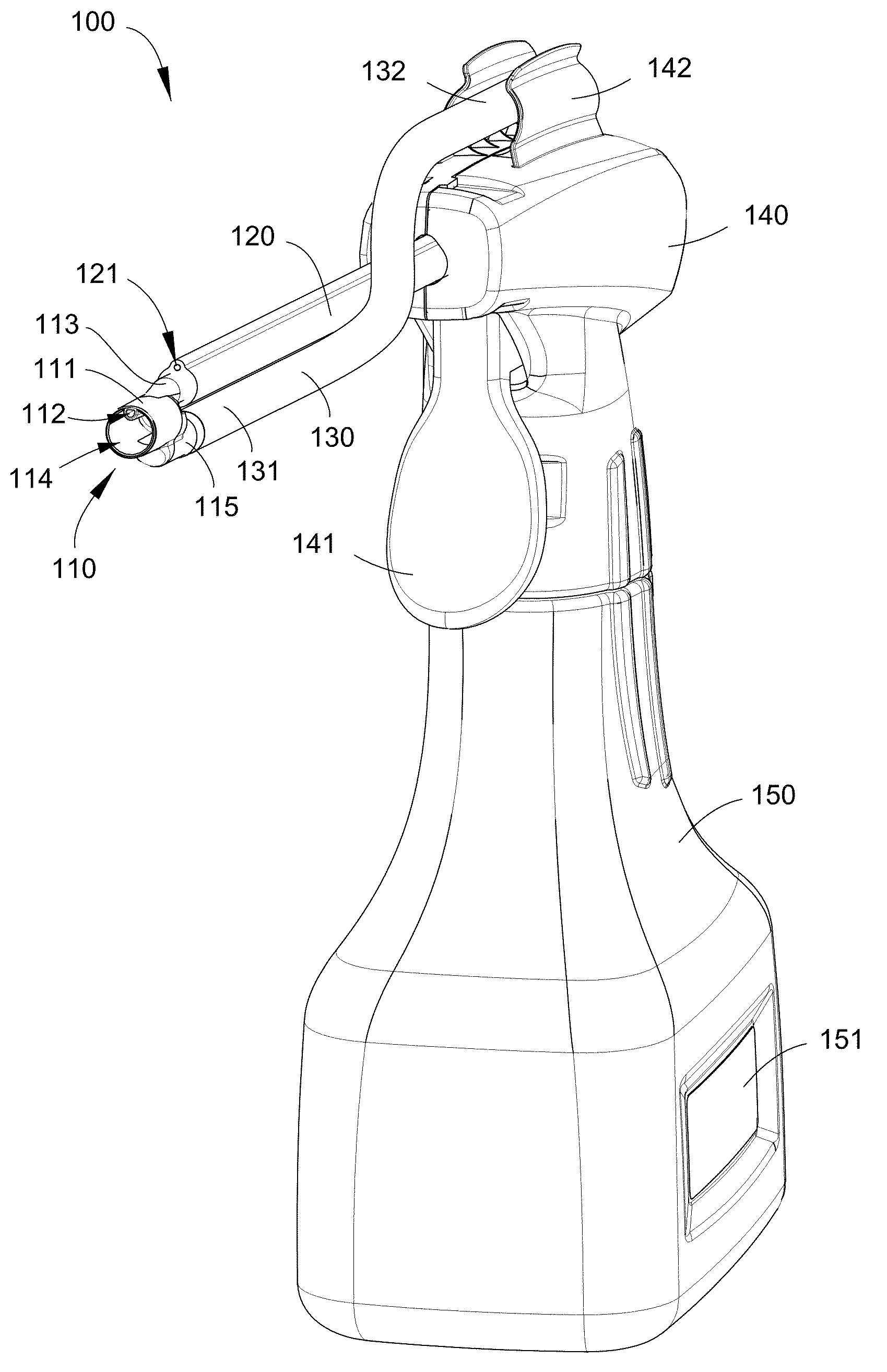
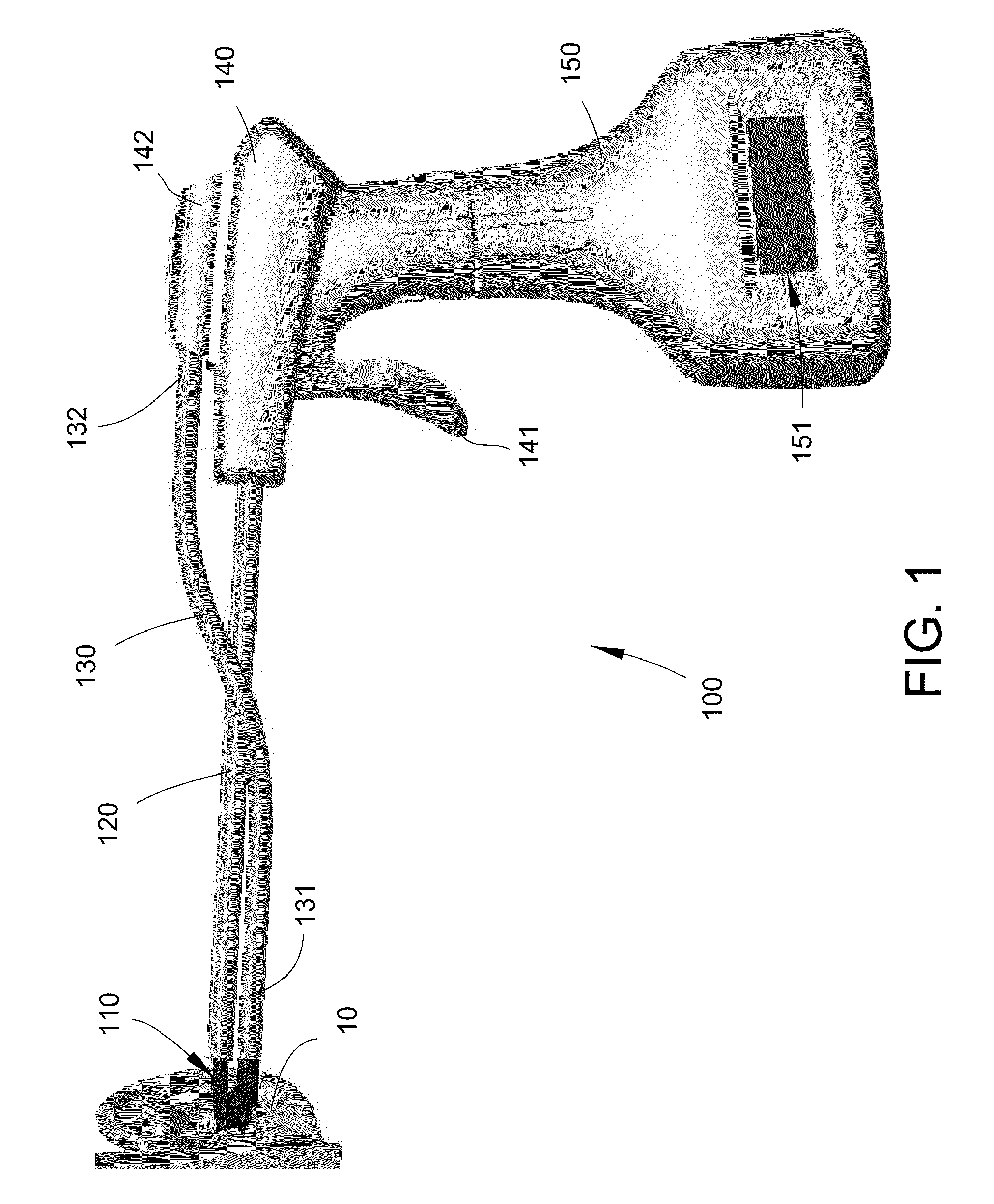
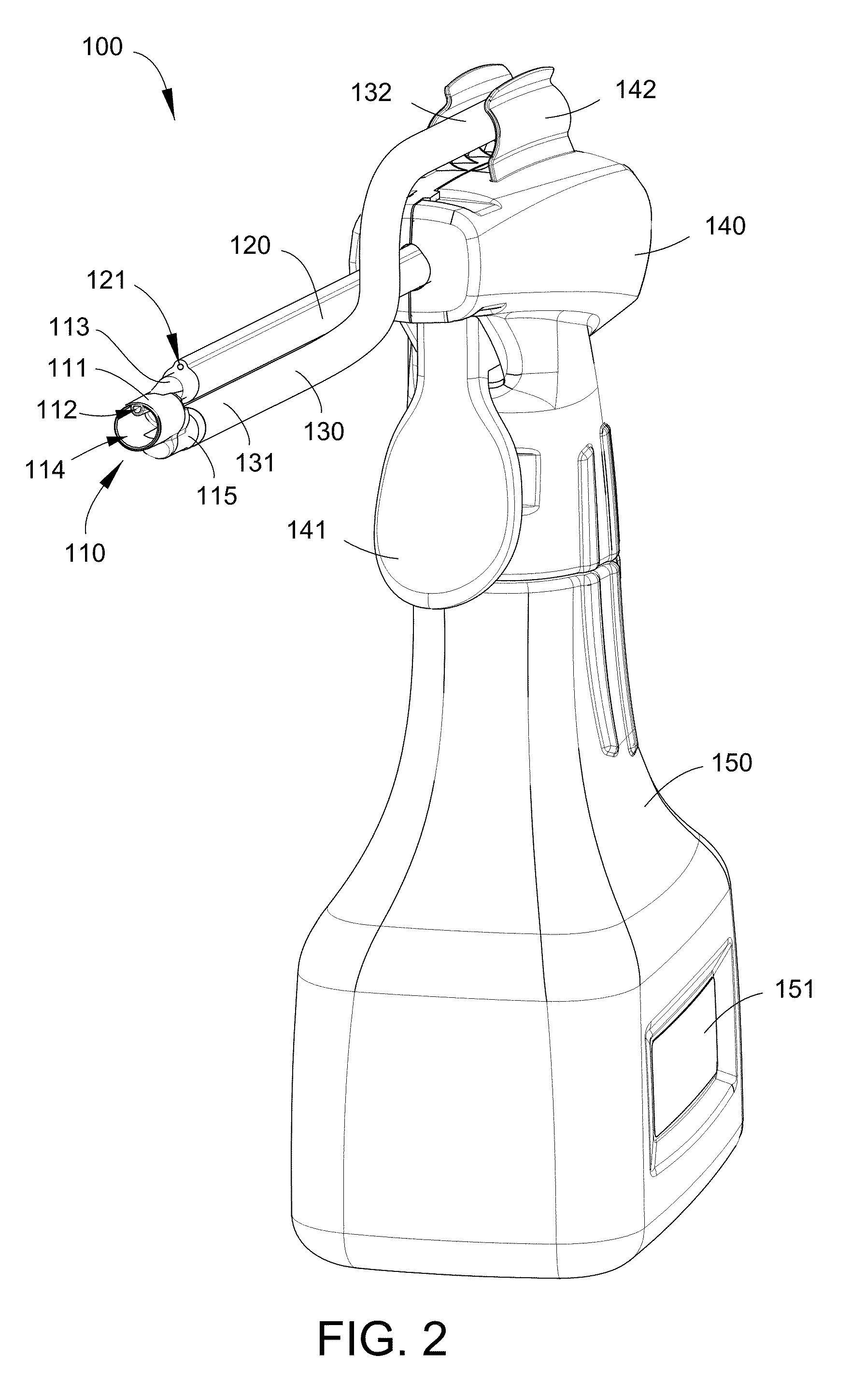
[0024]In its various embodiments, the present invention focuses on a device for irrigating a body cavity, particularly an external ear canal. Referring to FIGS. 1-2, in one embodiment, an applicator 110 of the device 100 may be inserted into the external ear canal of ear 10. A feeding tube 120 connects the applicator 110 to a pump 140, which has a trigger 141 biased outward and a holder 142. A drain tube 130 connects to the applicator 110 with a first end 131 and to a vacuum line (not shown) with a second end 132 wherein the holder 142 may support a junction of the second end 132 and the vacuum line. A container 150 with a temperature indicator 151 may be fastened to the pump 140.

[0025]For the purpose of current disclosure, term ‘pump’ means ...


PUM


Abstract

A hand-held disposable body cavity irrigation device comprises a pump with an inlet and an outlet, a container for lavage fluid fastened removably to said pump, an applicator having an insertion tip, and divided longitudinally into an injection chamber with a first fitting and a drain chamber with a second fitting, and a first tube connecting said outlet to the first fitting wherein the first tube comprises at least one malleable element embedded longitudinally into an elastic wall, said inlet communicates with the lavage fluid within the container, and the drain chamber is disposed predominantly below the injection chamber and has at least one vent beyond the insertion tip.

Description

BACKGROUND OF THE INVENTION[0001]The present invention relates to devices for injecting liquid into a body cavity to effect cleaning thereof and, more particularly, a device for irrigation of an external ear canal with lavage fluid.[0002]Various irrigation devices are known for cleaning human body cavities. For example, such devices are used routinely for cleaning the ears of a patient. Most commonly, a flexible bulb is fitted to a nozzle through which the lavage fluid is discharged into the ear canal of a patient.[0003]Bulb-type devices have several drawbacks. First, the bulb capacity limits the usage of the device since the bulb contains a relatively small quantity of the lavage fluid and, to fully irrigate a patient's ear, the bulb has to be refilled a number of times.[0004]Second, the pressure of the lavage fluid exiting the nozzle and impinging upon the ear canal can not be readily controlled in a reliable manner. This lack of control produces inconsistent results and can in tu...

Claims


Application Information

Patent Timeline
Patent Type & Authority Patents(United States)
IPC IPC(8): A61M1/00A61M5/178
CPCA61M3/0262A61M3/0283A61M3/0208A61M3/022A61M2205/3368A61M2210/0662A61M1/85A61M1/772
Inventor SHAPIRO, MISHAIL ALEXANDERPIRKHALO, ALEKSEYKHODOR, LEONID
Owner INSPECTOR MEDICAL
Why Eureka
Try Eureka