Infusion fluid heating apparatus

a technology of infusion fluid and heating apparatus, which is applied in the field of improvement of infusion fluid heating apparatus, can solve the problems of limited maximum flow, and achieve the effect of relatively small volume of the bag

Inactive Publication Date: 2011-08-02
OGAWA & CO LTD
View PDF13 Cites 2 Cited by
  • Summary
  • Abstract
  • Description
  • Claims
  • Application Information

AI Technical Summary

Benefits of technology

[0007]The invention was accomplished against the above background, and has an object to provide an infusion fluid heating apparatus which is versatile enough to be applicable to various infusion tubes with different length dimensions, and which can also increases the maximum infusion fluid flow amount for an infusion bag with a long infusion tube.
[0009]As described above, the tube fitting groove formed on one surface of the heating plate receives the infusion tube in a first length between the inlet opening and the outlet opening both opened at the end surfaces of the heating plate, and also receives the infusion tube in a second length which is shorter than the first length. Therefore, the tube fitting groove uses the second length for a relatively short infusion tube, capable of heating the tube appropriately and achieving high versatility. In addition, the tube fitting groove uses the first length for an infusion bag with a long infusion tube, capable of heating the tube appropriately and increasing the maximum infusion fluid flow amount.
[0010]Preferably, the tube fitting groove of the heating plate includes a basic groove formed in the first length between the inlet opening and the outlet opening, and a shunting groove shunting the basic groove in a middle thereof so that the second length is defined between the inlet opening and the outlet opening. This enables the application of a part of the basic groove to both cases of the first length of the infusion tube being inserted and where the second length of the infusion tube being inserted. Thus, size of the heating plate is made compact.
[0011]Further, preferably, the infusion fluid heating apparatus further comprises a case to which the heating plate is detachably attached. The heating plate in formed on other surface thereof a second tube fitting groove having a different sectional shape from the tube fitting groove formed on the one surface. This enables heating of the infusion tubes with different sectional shapes or diameter dimensions, thereby further improving versatility.
[0012]Further, preferably, the second tube fitting groove receives the infusion tube in a third length between an inlet opening and an outlet opening both opened at the end surface of the heating plate, and also receives the infusion tube in a third length which is shorter than the first length. As a result, on the other surface of the heating plate, the groove can use the fourth length for a relatively short infusion tube, making is possible to heat the tube appropriately and achieve high versatility. Additionally, the groove can use the third length for an infusion bag with a long infusion tube, making is possible to heat the tube appropriately and increase the maximum infusion fluid flow, thereby achieving higher versatility.
[0014]Further, preferably, the case is provided with an infusion bag containing the infusion fluid, in place of the heating plate. This enables heating of an infusion fluid even if the infusion tube is extremely short, provided that the volume of the bag is relatively small.

Problems solved by technology

Consequently, in order to improve versatility, the heating length of a heating plate has to be small to heat a short infusion tube, which causes a disadvantage of a limited maximum flow when the plate is used for a long infusion tube.

Method used


Image

  • Infusion fluid heating apparatus
  • Infusion fluid heating apparatus
  • Infusion fluid heating apparatus

Examples


embodiment

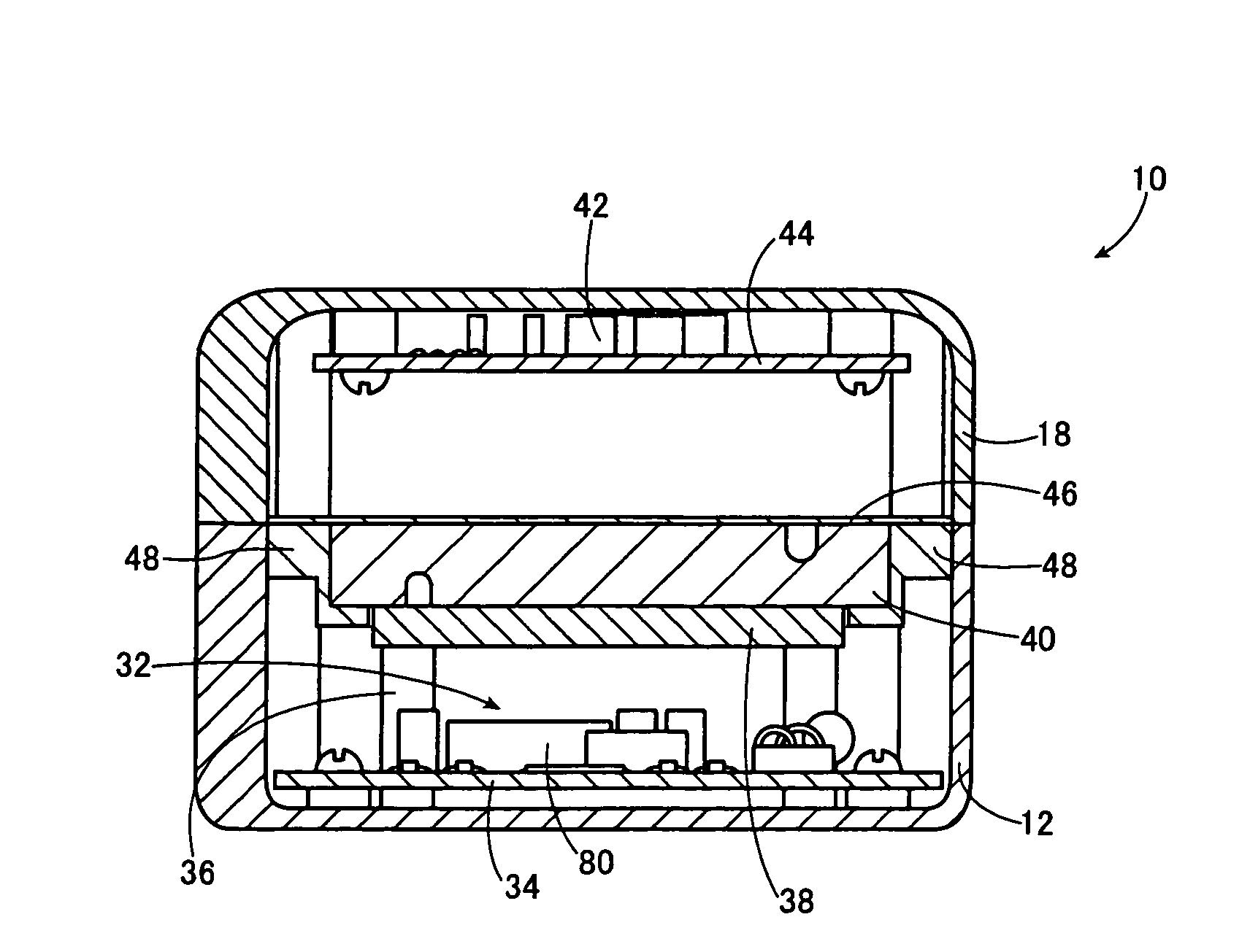
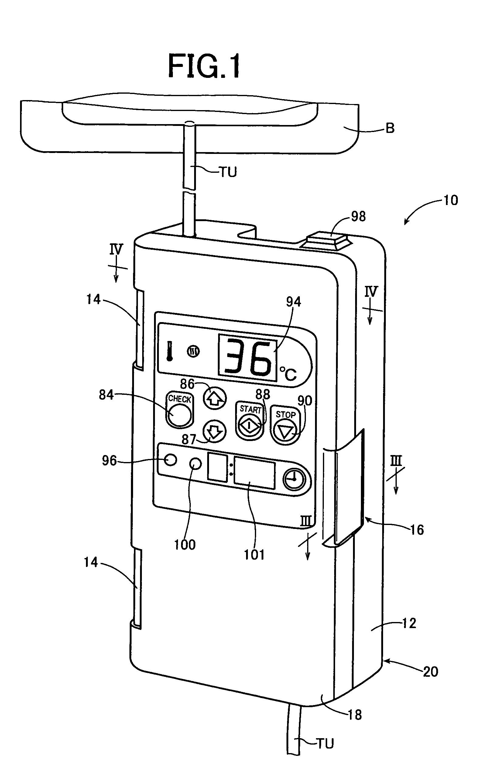
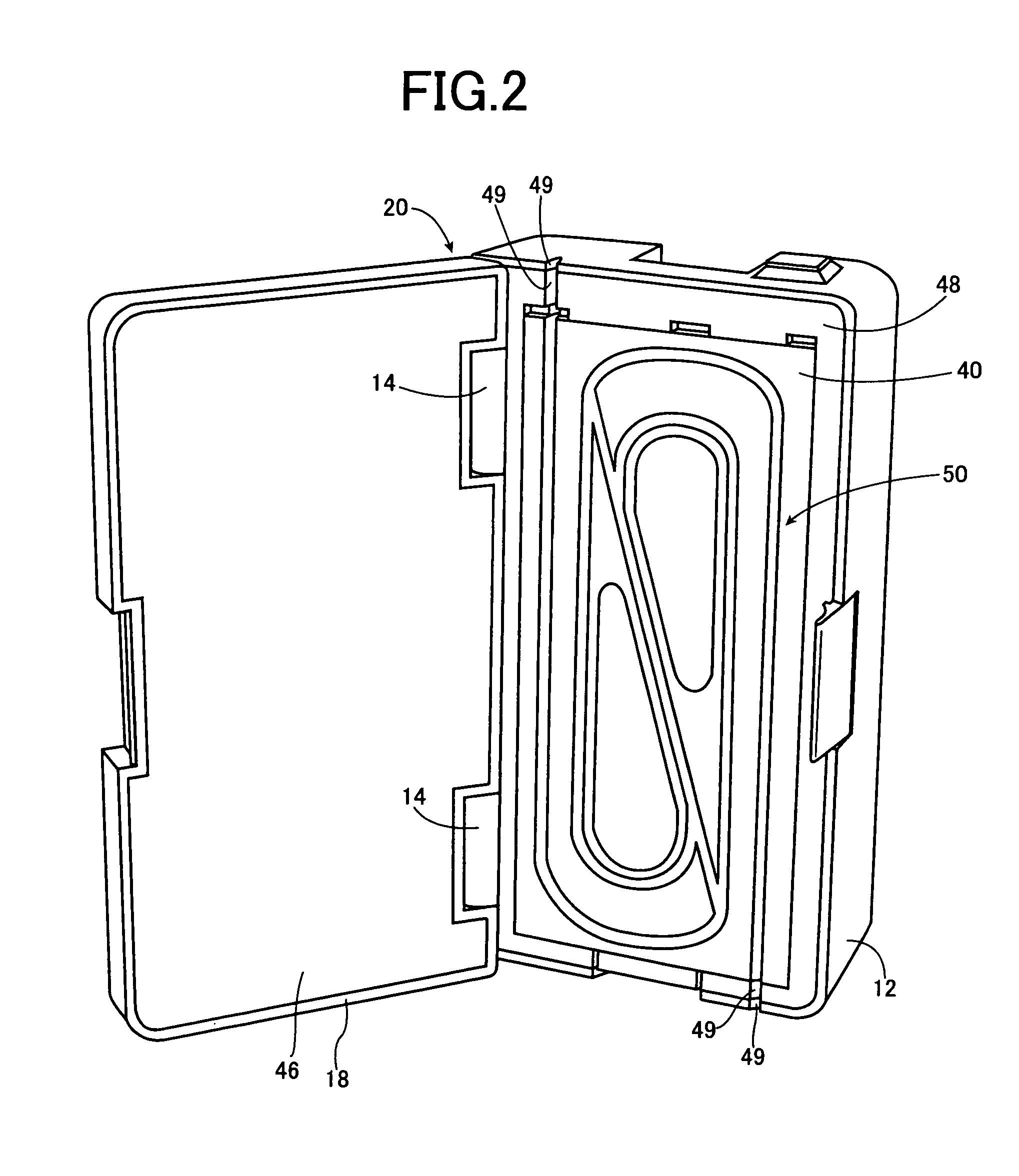
[0026]FIG. 1 is a perspective view illustrating structure of an infusion fluid heating apparatus 10 which is a first embodiment of the invention, and FIG. 2 is a perspective view thereof with the lid thereof open. As shown in these figures, the infusion fluid heating apparatus 10 includes a case 20 having a case body 12 and a lid 18. The case body 12 is made of a synthetic resin, and forms a rectangular parallelepiped-shaped housing with one face open. The lid 18 is pivotally attached via a pair of hinges 14 to one of paired long sides forming a part of the rectangular opening edge of the case body 12. The lid 18 is locked with a locking device 16 made of a synthetic resin and provided in a longitudinal center of other long side. The lid 18 has a thickness (depth) smaller than that of the case body 12, but also forms a rectangular parallelepiped-shaped housing with its opposite face to the case body 12 being open. The lid 18 is connected to the case body 12 via the pair of hinges 14...


PUM


Abstract

An infusion fluid heating apparatus applicable to various types of infusion tube with different length dimensions includes a front-side tube fitting groove or a rear-side tube fitting groove formed on one of surfaces of a heating plate that receives an infusion tube in a first length between an inlet opening and an outlet opening open at the end surfaces of the heating plate. The groove also receives the infusion tube in a second length shorter than the first length. Therefore, the groove uses the second length for a relatively short infusion tube, capable of heating the tube appropriately and achieving high versatility. In addition, the tube fitting groove uses the first length for an infusion bag with a relatively long infusion tube, capable of heating the tube appropriately and increasing the maximum infusion fluid flow.

Description

TECHNICAL FIELD[0001]The prevent invention relates to improvement of an infusion fluid heating apparatus for pre-heating infusion fluid up to a suitable temperature, when introducing the infusion fluid into a living body mainly in a medical field.BACKGROUND ART[0002]In actual medical field, an infusion fluid such as blood, a nutrition liquid, a liquid medicine is occasionally introduced into a living body. In such a case, in general, the fluid is packed in an infusion bag or bottle hung on a stand, and is injected into a blood vessel of a living body, etc. through a drip tube, a roller clamp, an infusion tube, and an injection needle connected thereto.[0003]Such infusion fluid is often stored at a relatively low temperature in response to the requirement of quality preservation. Accordingly, for example, when infusion is needed in emergency surgery, etc., the infusion fluid may be required to be heated up to around the living body temperature as quickly as possible. For this reason,...

Claims


Application Information

Patent Timeline
Patent Type & Authority Patents(United States)
IPC IPC(8): A61F7/12A61M37/00A61F7/00
CPCA61M5/44A61M5/1414
Inventor OGAWA, GENSHIROU
Owner OGAWA & CO LTD
Why Eureka
Try Eureka