Illuminated switch device

a technology of illumination switch and illumination, which is applied in the direction of emergency actuators, electrical devices, legends, etc., can solve the problems of difficult to obtain good lighting quality, less likely to reach the source, less likely to reach the first illuminated region, etc., to prevent light leakage, prevent an increase in the diameter of the operating body or the casing, and good lighting quality

Active Publication Date: 2011-08-02
ALPS ALPINE CO LTD
View PDF7 Cites 3 Cited by
  • Summary
  • Abstract
  • Description
  • Claims
  • Application Information

AI Technical Summary

Benefits of technology

[0010]In the illuminated switch device having the above-mentioned structure, since the leading end portion of the light-shielding wall, which is formed on the rear surface of the upper plate of the operating body, is opposite to the leading end portion of the partition wall, which is formed on the inner bottom of the casing, so as to approach or separate from the leading end portion of the partition wall, a gap whose length is variable according to the pressing operation of the operating body is formed between the two leading end portions. However, since the gap between the protruding portion and the concave groove is greatly curved, light emitted from the first light source is less likely to reach the second illuminated region through the gap, and light emitted from the second light source is less likely to reach the first illuminated region through the gap. Therefore, it is possible to prevent light leakage between two light sources using one light-shielding wall and one partition wall having leading end portions opposite to each other. As a result, it is possible to obtain a good lighting quality while preventing an increase in the diameter of an operating body or a casing.

Problems solved by technology

As a result, it is difficult to obtain a good lighting quality.
However, since the gap between the protruding portion and the concave groove is greatly curved, light emitted from the first light source is less likely to reach the second illuminated region through the gap, and light emitted from the second light source is less likely to reach the first illuminated region through the gap.

Method used


Image

  • Illuminated switch device
  • Illuminated switch device
  • Illuminated switch device

Examples


first embodiment

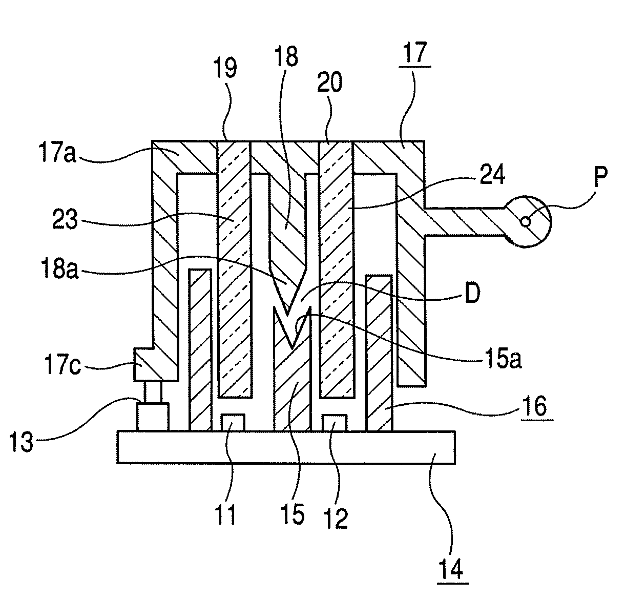
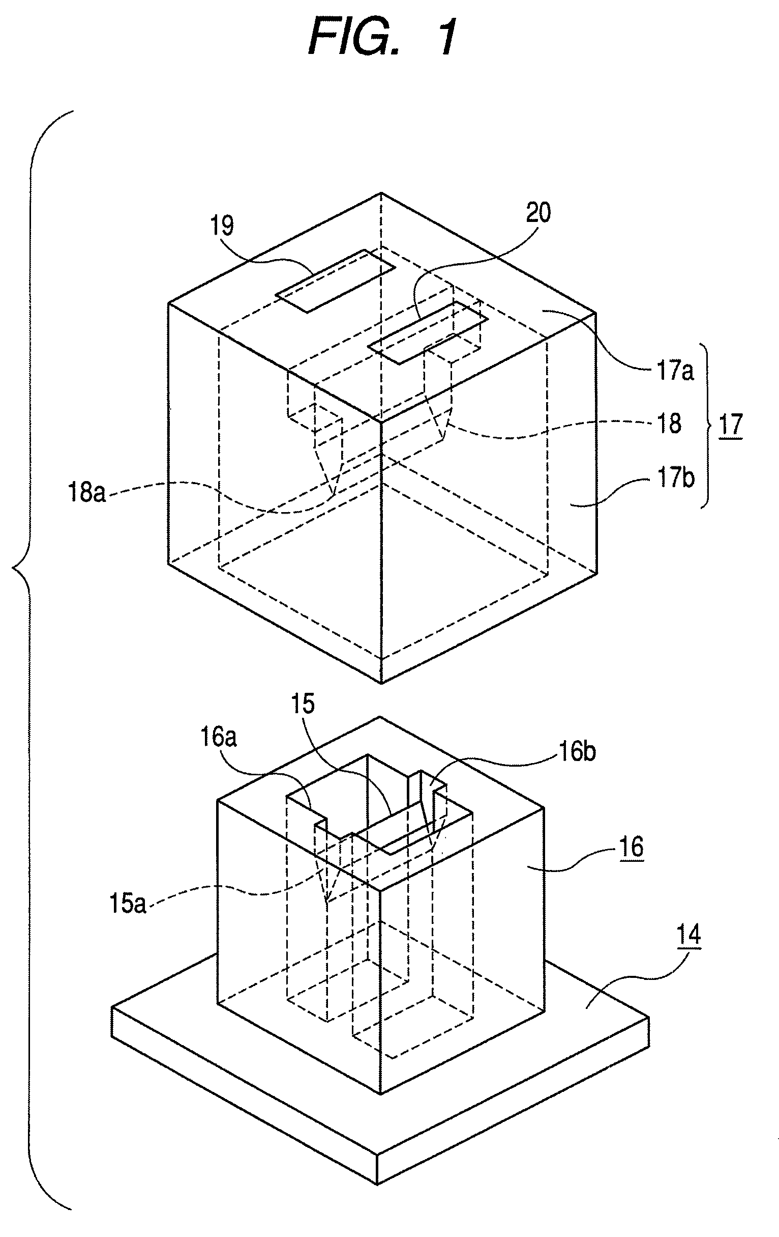
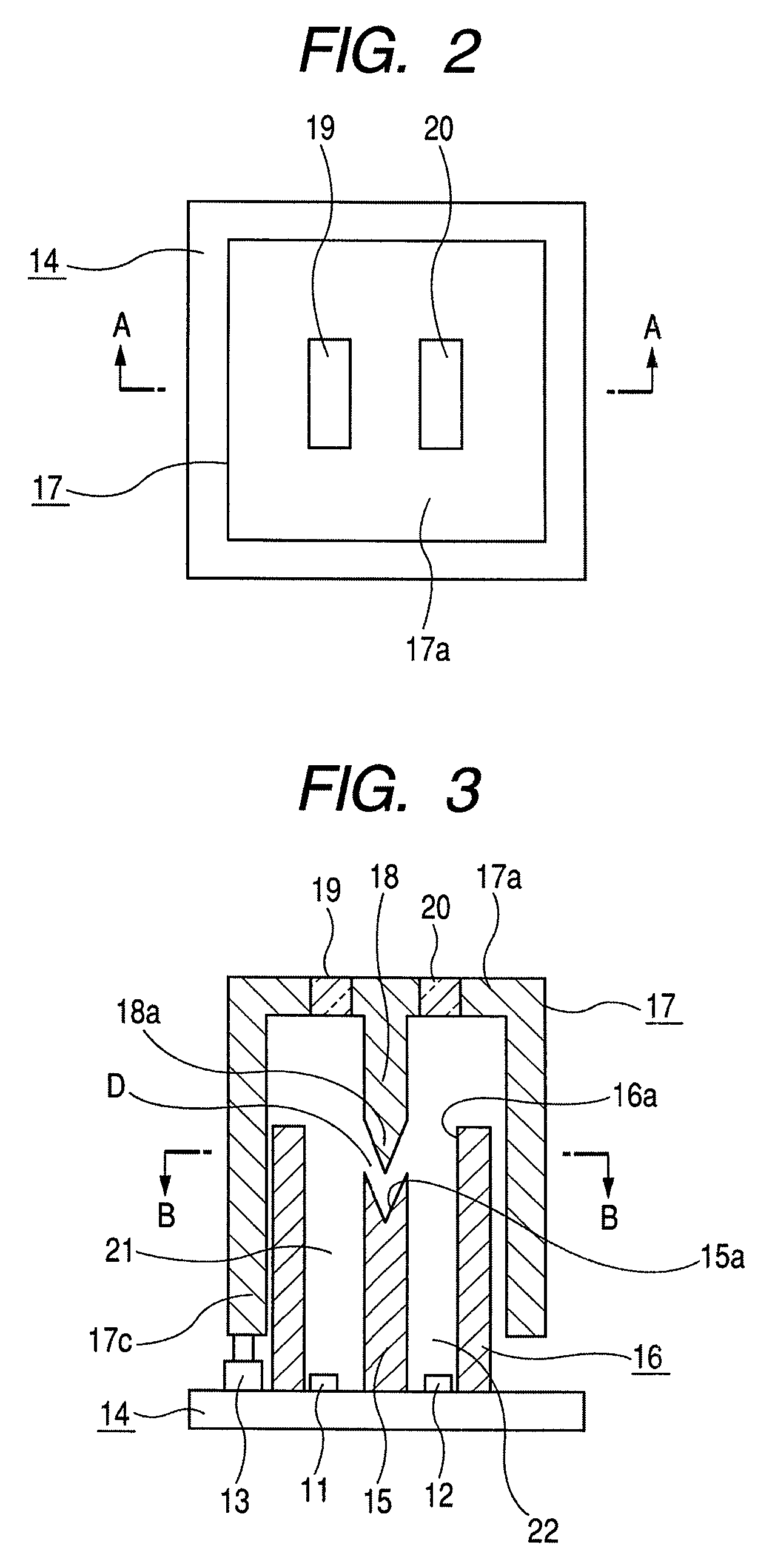
[0018]Hereinafter, exemplary embodiments of the invention will be described with reference to the accompanying drawings. FIG. 1 is an exploded perspective view illustrating an illuminated switch device according to the invention. FIG. 2 is a plan view illustrating the switch device. FIG. 3 is a cross-sectional view taken along the line III-III of FIG. 2. FIG. 4 is a cross-sectional view taken along the line IV-IV of FIG. 3.

[0019]The illuminated switch device shown in the drawings includes: a bottom plate member (substrate) 14 having a first light source 11, a second light source 12, and a push switch 13 mounted thereon; a casing 16 that is provided on the bottom plate member 14, has an open upper end 16a, and includes a partition wall 15 provided therein; and an operating body 17 that has a light-shielding wall 18 provided on the rear surface of an upper plate 17a, is arranged so as to close the open end 16a, and can be pressed. A first illuminated region 19 and a second illuminated...

second embodiment

[0029]In the second embodiment, the pivot P of the operating body 17 is set at a position that is higher than the protruding portion 18a, and the light-shielding wall 18 deviates from the extension of the partition wall 15 so as to be further away from the pivot P than the extension. However, the invention is not limited thereto. The pivot P of the operating body 17 may be provided at a position that is lower than the protruding portion 18a. In this case, the light-shielding wall 18 may deviate from the extension of the partition wall 15 so as to be closer to the pivot P than the extension.

[0030]In the above-described embodiments, two illuminated regions 19 and 20 provided in the operating body 17 are individually illuminated by the light sources 11 and 12. However, the invention is not limited thereto. The number of light sources may increase, and illuminated regions corresponding to the number of light sources may be provided in the operating body. In this case, the invention may ...


PUM


Abstract

Disclosed is an illuminated switch device capable of effectively preventing light leakage between different light sources, thereby obtaining a good lighting quality, while reducing the overall size of the switch device. The illuminated switch device includes: a casing that has an open upper end and a partition wall provided therein and is formed on a bottom plate member having light sources and a push switch mounted thereon; and an operating body that has a light-shielding wall provided on the rear surface of an upper plate, is arranged so as to close the open end, and can be pressed. First and second illuminated regions to which light components are emitted from first and second light sources are provided on the upper plate. A protruding portion is formed at a leading end portion of a light-shielding wall, and a concave groove is provided at a leading end portion of a partition wall. The leading end portions are opposite to each other such that they can approach or separate from each other. At least a part of the protruding portion is arranged in the concave groove, and a gap is formed between the leading ends of the protruding portion and the concave portion.

Description

CLAIM OF PRIORITY[0001]This application claims benefit of the Japanese Patent Application No. 2007-286020 filed on Nov. 2, 2007, the entire contents which are hereby incorporated by reference.BACKGROUND[0002]1. Technical Field[0003]The present invention relates to an illuminated switch device in which a plurality of light sources are provided in a casing so as to correspond to a plurality of illuminated regions that are provided on an upper plate of an operating body, and more particularly, to a technique for preventing light leakage between different light sources.[0004]2. Related Art[0005]The structure of this type of illuminated switch device according to the related art will be described with reference to FIG. 7. In a casing 1, a first light source 3 and a second light source 4 are provided on a bottom plate member 2 so as to be parallel to each other, and a partition wall 5 is formed between the light sources 3 and 4. In addition, a switch element (not shown) is mounted on the ...

Claims


Application Information

Patent Timeline
Patent Type & Authority Patents(United States)
IPC IPC(8): H01H9/00
CPCH01H9/182H01H13/023H01H2013/026H01H2219/062H01H2219/064H01H2221/016
Inventor MCCURDY, ANTHONYHOSHI, TAKAYOSHIIMAI, TOSHIO
Owner ALPS ALPINE CO LTD
Why Eureka
Try Eureka