Printer having printing unit and movable media unit

a printing unit and movable media technology, applied in the field of printing machines, can solve the problems of increasing the disadvantages of prior art and problems, affecting the operation of the printer, and avoiding the damage of the printing unit, so as to minimize the cost of low tolerance manufacturing and avoid the effect of damage to the printing uni

Inactive Publication Date: 2011-08-09
CONTINENTAL AUTOMOTIVE GMBH
View PDF16 Cites 0 Cited by
  • Summary
  • Abstract
  • Description
  • Claims
  • Application Information

AI Technical Summary

Benefits of technology

[0007]The invention eliminates the problem, which prevails in the prior art, of play and tolerance compensation in the guide of the transport unit which can be moved relative to the printing unit, unlike the concept of wishing to reproduce the position of the transport unit after every movement period sufficiently exactly in the overall arrangement for a satisfactory print quality. Instead, according to the invention, only the printing unit is positioned sufficiently exactly relative to the carrier with the media unit, it being possible for the combination of these two modules to be arranged in the overall construction of the printer with the comparatively large positional tolerances. According to the invention, this possibility opens up because the printing unit can move in the overall construction of the printer and can be oriented relative to the media unit when the latter is pushed into the housing. In this way, it is possible for the first time, while avoiding expensive low tolerances of the guide components of the carrier, to combine a satisfactory print quality with comfortable print-media changing in a printer of the generic type.
[0008]The media unit advantageously has a carrier which can be moved, relative to the printing unit, in a push-in direction into an operating position and counter to the push-in direction out of an operating position, and can be moved at least partly out of the housing. This carrier can serve to accommodate additional components and is expediently composed of a robust material which largely avoids undesired deformations in the event of a correspondingly rigid static design.
[0009]In order that the printing unit is always at the spacing required for a satisfactory printed image from the medium to be printed, it is expedient if the printing unit can be moved in the housing, in the push-in direction and counter to the push-in direction. Moreover, further degrees of freedom of the movability are appropriate, even perpendicularly with respect to the push-in direction, in order that the position of the printed image on the medium is corrected with the pushing-in action. In addition, it is expedient if the printing unit also has translatory degrees of freedom, with the result that an oblique position of the media unit with respect to the printing unit can be corrected with the pushing-in action. To this extent, what is known as a floating mounting of the printing unit in the housing, which mounting combines the abovementioned degrees of freedom with one another, is extremely beneficial for the print quality.
[0011]One advantageous development of the invention provides for the printing unit to have a first contact region and the housing to have a second contact region and, by means of the force of the elastic element, the printing unit to move with the first contact region in the direction of the second contact region, in a rest position which is not the operating position, the first contact region to bear against the second contact region and the printing unit to be clamped in this way between the elastic element and the second contact region by means of the force of the elastic element. Clamping the printing unit in a manner according to the invention in the housing by means of the elastic element and the interaction of contact regions has the advantage that the printing unit it always secured in a defined position and cannot perform any uncontrolled movements in the housing. Damage to the printing unit can be avoided in this way.
[0012]A further practical implementation of the invention provides for the carrier to have a first contact face, the printing unit to have a second contact face, and for the first and second contact faces to correspond with one another in such a way that, when the carrier is moved in the push-in direction, the first contact faces come into contact with the second contact faces, in each case in pairs. In this development of the invention, the advantages according to the invention come to bear in particular, because a one-off adjustment of the functional components with respect to the respective contact faces which is related in each case to the module is sufficient to ensure satisfactory operation of the printer. In addition, the contact faces can be configured to be comparatively small in relation to the guide faces of the carrier, which minimizes the costs of low-tolerance manufacture of the contact faces.
[0013]In order that there is not only satisfactory positional accuracy of the printing unit with respect to the carrier in the perpendicular direction of contact faces, but high accuracy of the positioning of the printing unit relative to the carrier prevails perpendicularly to the vertical axes of the contact faces, it is expedient if the printing unit has at least one first centering element and the carrier has at least one second centering element which corresponds to the first centering element, with the result that, when the carrier is moved in the push-in direction, the carrier and the printing unit are oriented in the housing by means of the centering elements in the operating position, relative to one another in the spacing direction, and / or are centered in at least one direction perpendicular with respect to the spacing direction. The centering elements can comprise pairs of interacting, oblique or conical faces, or of cones which interact with corresponding conical recesses. Here, it can also be advantageous if a centering element assumes the centering function only in one direction perpendicularly with respect to the vertical axis of the contact faces or the vertical movement axis. Furthermore, a fork-shaped centering element has proved to be appropriate, which interacts with a cylindrical corresponding part in such a way that the circumferential surface of the cylinder is guided by those flanks of the fork-shaped receptacle which face one another.

Problems solved by technology

However, the technical implementation of this inventive idea has proved problematical in the past.
The disadvantages of the prior art and the problems are increased additionally by the customary component tolerances which are already fixed from economic aspects.
In conjunction with the fixed component tolerances, the movement play which is definitely required for the transport unit leads to unacceptable print quality results.
However, the media change is comparatively complicated here, as the printing medium has to be threaded into the front part of the drawer.

Method used


Image

  • Printer having printing unit and movable media unit
  • Printer having printing unit and movable media unit
  • Printer having printing unit and movable media unit

Examples


Embodiment Construction

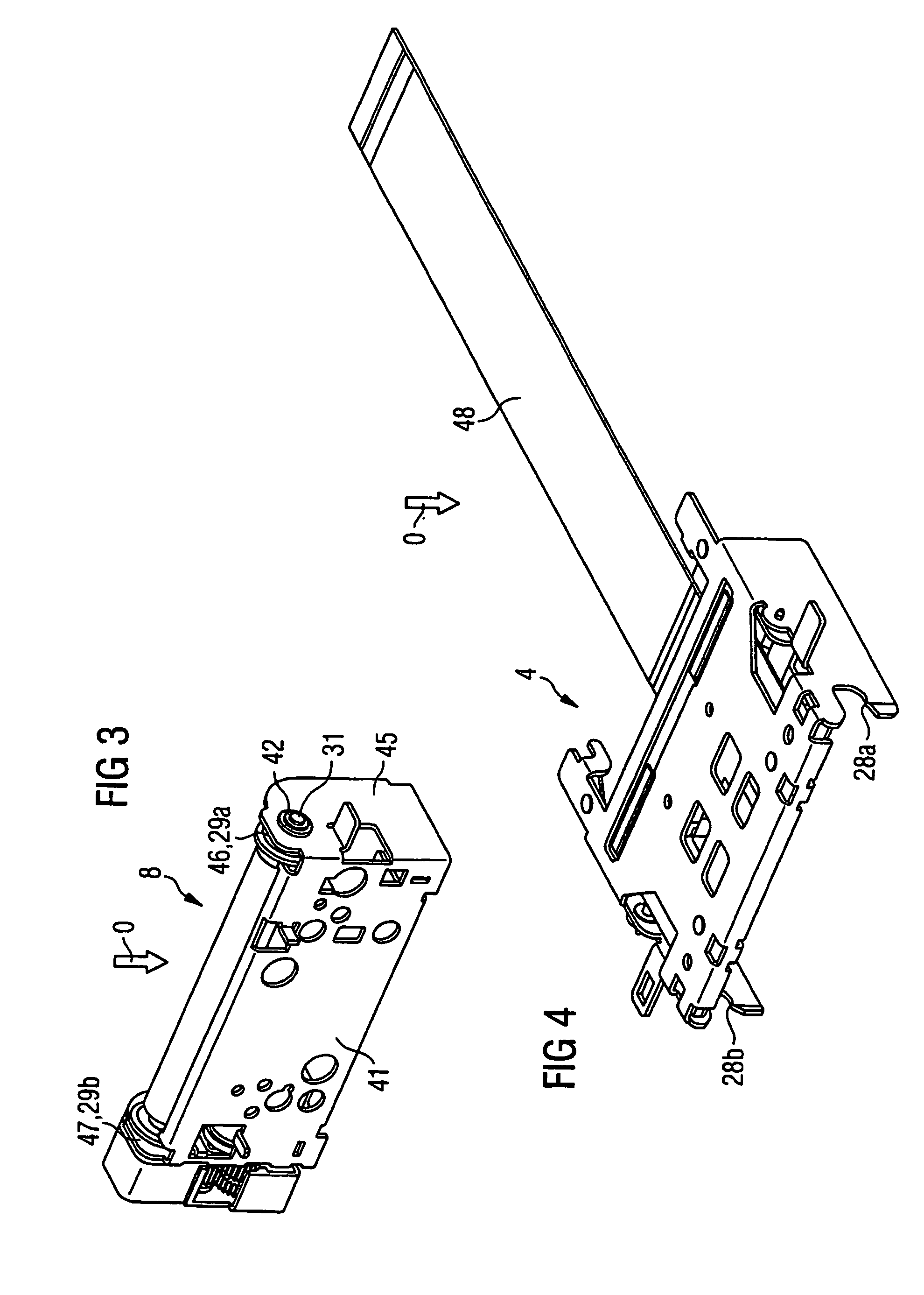
[0032]In the illustrations of a printer 1 in FIGS. 3 to 11, in each case an orientation direction which is denoted as above is symbolized by an arrow having the designation O.

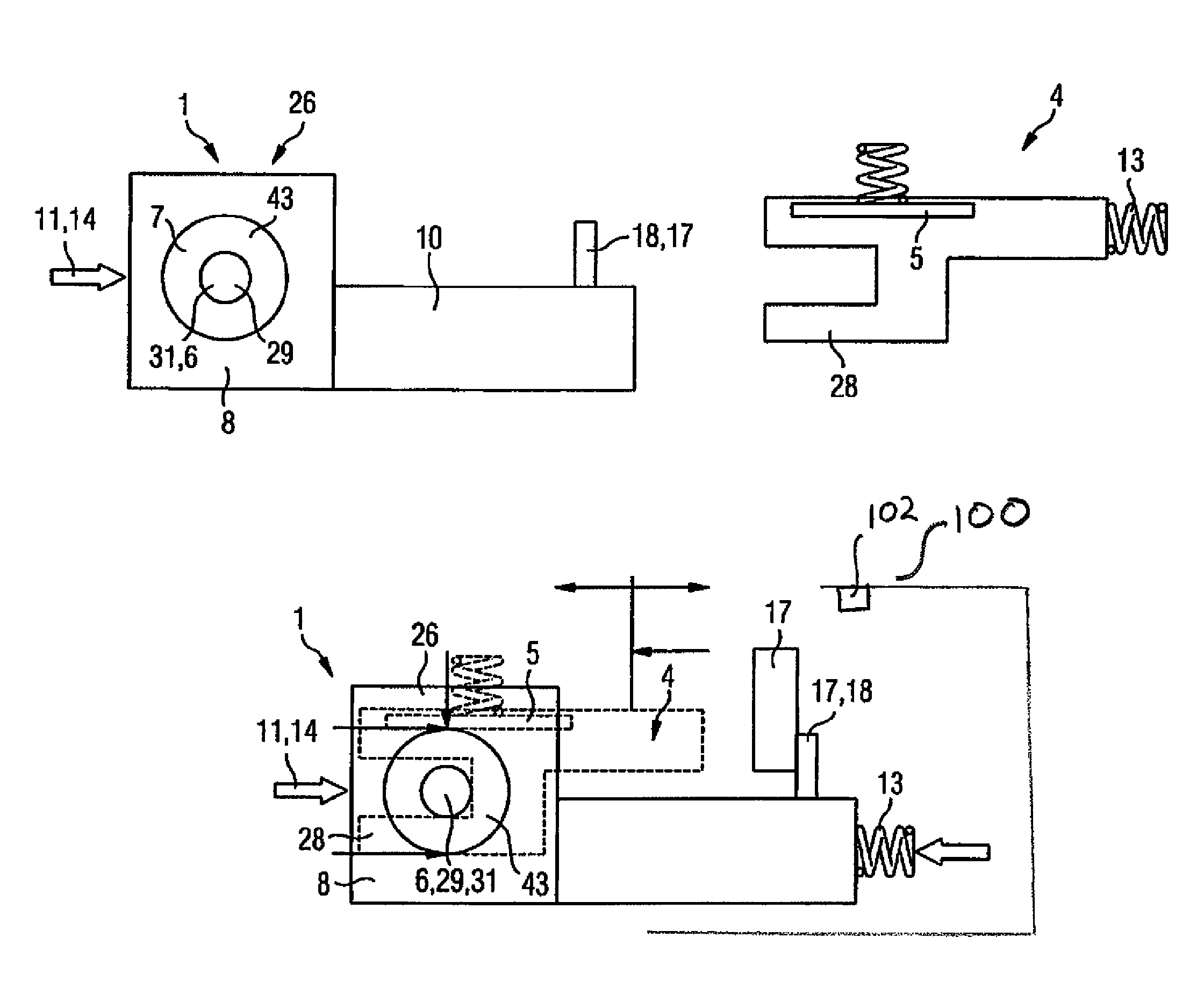
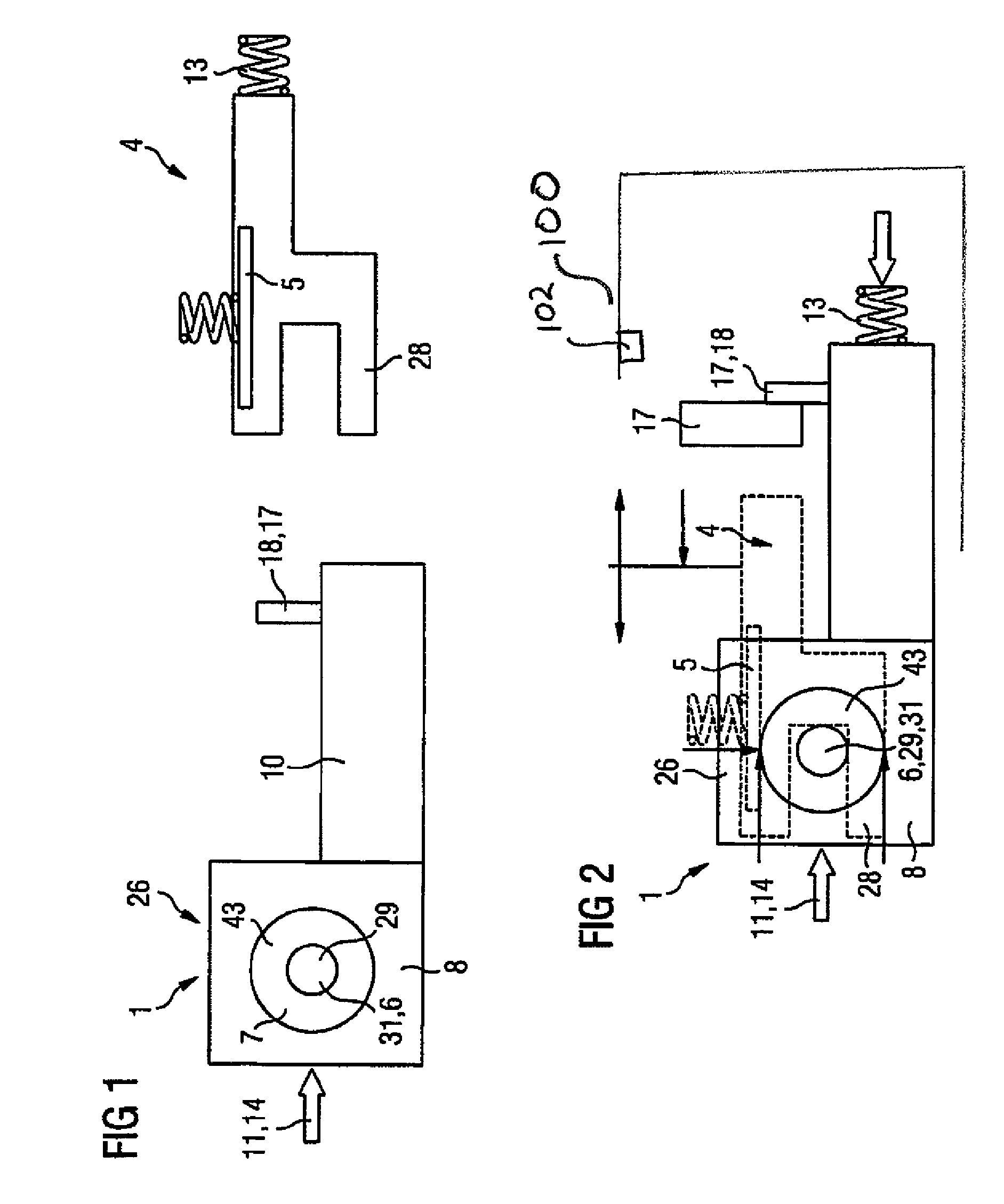
[0033]In the diagrammatic illustrations of a printer 1 in FIGS. 1 and 2, the media unit 26 is provided with the designation 26 and the printing unit 4 is provided with the designation 4. The media unit 26 comprises a transport unit 8 with a transport roll 43 which is mounted rotatably about a receptacle 6 which is configured as a shaft 31. The medium (not shown) to be printed, preferably paper of a paper roll, is configured as a tape spool and is arranged on a cylindrical receptacle (not shown). The transport unit 8 with the transport roll 43 and the shaft 31 is fastened to a carrier 10.

[0034]Movable parts 18 of a locking unit 17 are likewise a constituent part of the carrier 10.

[0035]The carrier 10 is mounted in a housing (not shown) such that it can move in and counter to a push-in direction 11. In order to c...


PUM


Abstract

A printer is disclosed having a media unit which can move relative to a printing unit. Until now, difficulties in aligning the media unit in the printer always resulted in a poor printing quality. To rectify this, the disclosed printer provides that the printing unit is designed so that it can move inside the housing, and elements are provided for aligning the printing unit with the media unit so that the printing unit and the media unit can be aligned with one another when the media unit is pushed in the direction of insertion. A resilient element enables the printing unit to be advantageously tensioned, in a manner that equalizes tolerances, against the support of the media unit in an operating position. This enables an advantageous equalization of work tolerances and positional tolerances, and the position of the print head relative to the medium to be printed.

Description

BACKGROUND OF THE INVENTION[0001]The invention relates to a printer, in particular a printer of a tachograph for a motor vehicle, having a housing, a printing unit, a media unit for accommodating the medium which is to be printed, which media unit has a carrier and can be moved jointly with the carrier, relative to the printing unit, in a push-in direction into an operating position and counter to the push-in direction out of an operating position, and can be moved at least partly out of the housing, and the carrier has lateral first guide elements, in the manner of a drawer, which interact with second guide elements in such a way that the carrier can be moved in the push-in direction and counter to the push-in direction out of the housing.[0002]An apparatus of this type is already known from German utility model 299 20 901.6 which deals with a tachograph of flat, parallelepiped-shaped design. The thermal printing head and the transport roller for the transport of the printing mediu...

Claims


Application Information

Patent Timeline
Patent Type & Authority Patents(United States)
IPC IPC(8): B41J2/32B41J25/312G01D15/32G07C7/00
CPCB41J2/32B41J25/312G01D15/32G07C7/00B41J2202/31
Inventor RIESTER, THOMASKIRNER, HERBERTHUEGLE, AXEL
Owner CONTINENTAL AUTOMOTIVE GMBH
Why Eureka
Try Eureka