Air cleaner unit for vehicle and fan shroud having the same

a technology for air cleaners and vehicles, applied in the direction of liquid fuel engines, combustion air/fuel air treatment, separation processes, etc., can solve the problem of not increasing the size of the air cleaner unit, and achieve the effect of increasing the suctioning surface area of the air cleaner element, and increasing the volume of the predetermined spa

Inactive Publication Date: 2011-08-16
DENSO CORP
View PDF24 Cites 8 Cited by
  • Summary
  • Abstract
  • Description
  • Claims
  • Application Information

AI Technical Summary

Benefits of technology

[0006]In an air cleaner unit, it will be considered to increase the inside space of the air cleaner housing so as to restrict entry of water into an engine. In such a case, an air cleaner housing will be arranged in a location without interfering with peripheral devices, and a duct is coupled to the air cleaner housing for introducing air to the air cleaner housing. However, an entire size of the air cleaner unit increases, and resistance to flow of the air increases because the length of air path is increases.
[0007]The present invention is made in view of the foregoing matter, and it is an object of the present invention to provide an air cleaner unit for a vehicle, capable of reducing an entire size and reducing resistance to flow of intake air to be introduced in an engine of the vehicle.
[0009]In such a configuration, the predetermined space is provided under the air cleaner element within the air cleaner housing, a suctioning surface area of the air cleaner element is increased. In addition, since the bottom wall of the air cleaner housing has the projecting portion between the arcuate portions, a vertical dimension of the predetermined space is larger at a location corresponding to the projecting portion than locations corresponding to the arcuate portions. The volume of the predetermined space is increased by the projecting portion. In other words, the volume of the predetermined space is increased by effectively using the space above the ring portions of the fan shroud. Accordingly, resistance to flow of the intake air through the air cleaner element is reduced. Further, an entire size of the air cleaner unit is not increased. For example, the volume of the air cleaner housing is increased without increasing the height of the air cleaner housing in an engine compartment of the vehicle.
[0010]According to a second aspect of the present invention, an air cleaner unit for a vehicle includes an air cleaner element and an air cleaner housing. The air cleaner housing defines an intake air passage through which an intake air to be introduced in a engine of the vehicle flows. The air cleaner housing is to be arranged above ring portions of a fan shroud. The air cleaner housing has a base rectangular dimension having a longitudinal axis in an alignment direction of the ring portions. The air cleaner element disposed in the air cleaner housing such that a cleaner upstream space is provided between a lower surface of the air cleaner element and an inner bottom surface of the air cleaner housing. The cleaner upstream space is configured to increase resistance to flow of the intake air and capture contaminants such as water and fine particles removed from the intake air. The air cleaner housing has a space increasing projection projecting downwardly beyond the base rectangular dimension at its bottom. The space increasing projection is configured to increase the volume of the cleaner upstream space.
[0011]In such a configuration, the volume of the cleaner upstream space is increased by the projecting portion. That is, the volume of the cleaner upstream space is increase by effectively using the space above the ring portions of the fan shroud. Thus, an entire size of the air cleaner unit is not increased. Further, resistance to flow of the intake air through the air cleaner element is reduced.

Problems solved by technology

Further, an entire size of the air cleaner unit is not increased.

Method used


Image

  • Air cleaner unit for vehicle and fan shroud having the same
  • Air cleaner unit for vehicle and fan shroud having the same
  • Air cleaner unit for vehicle and fan shroud having the same

Examples


first embodiment

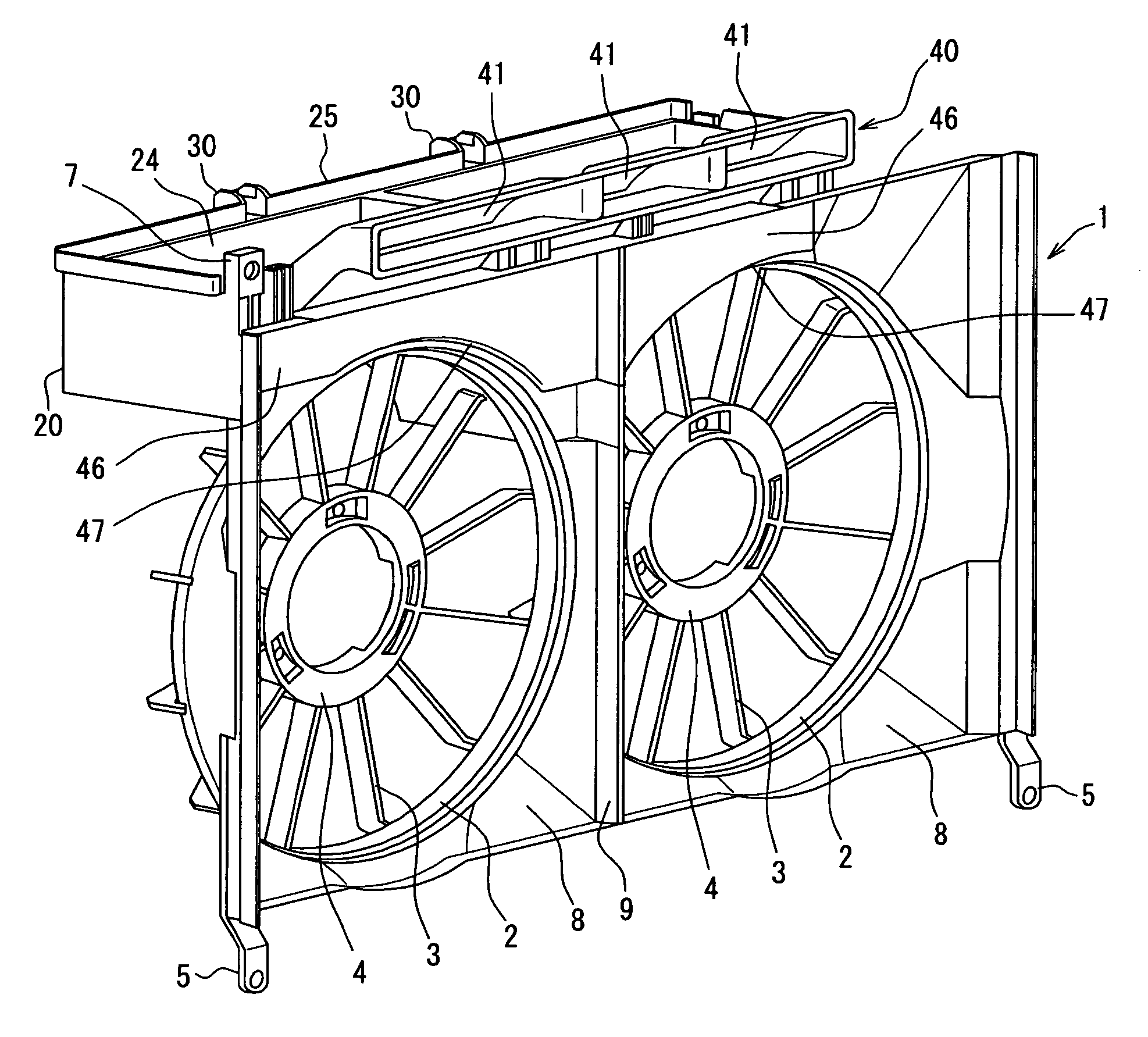
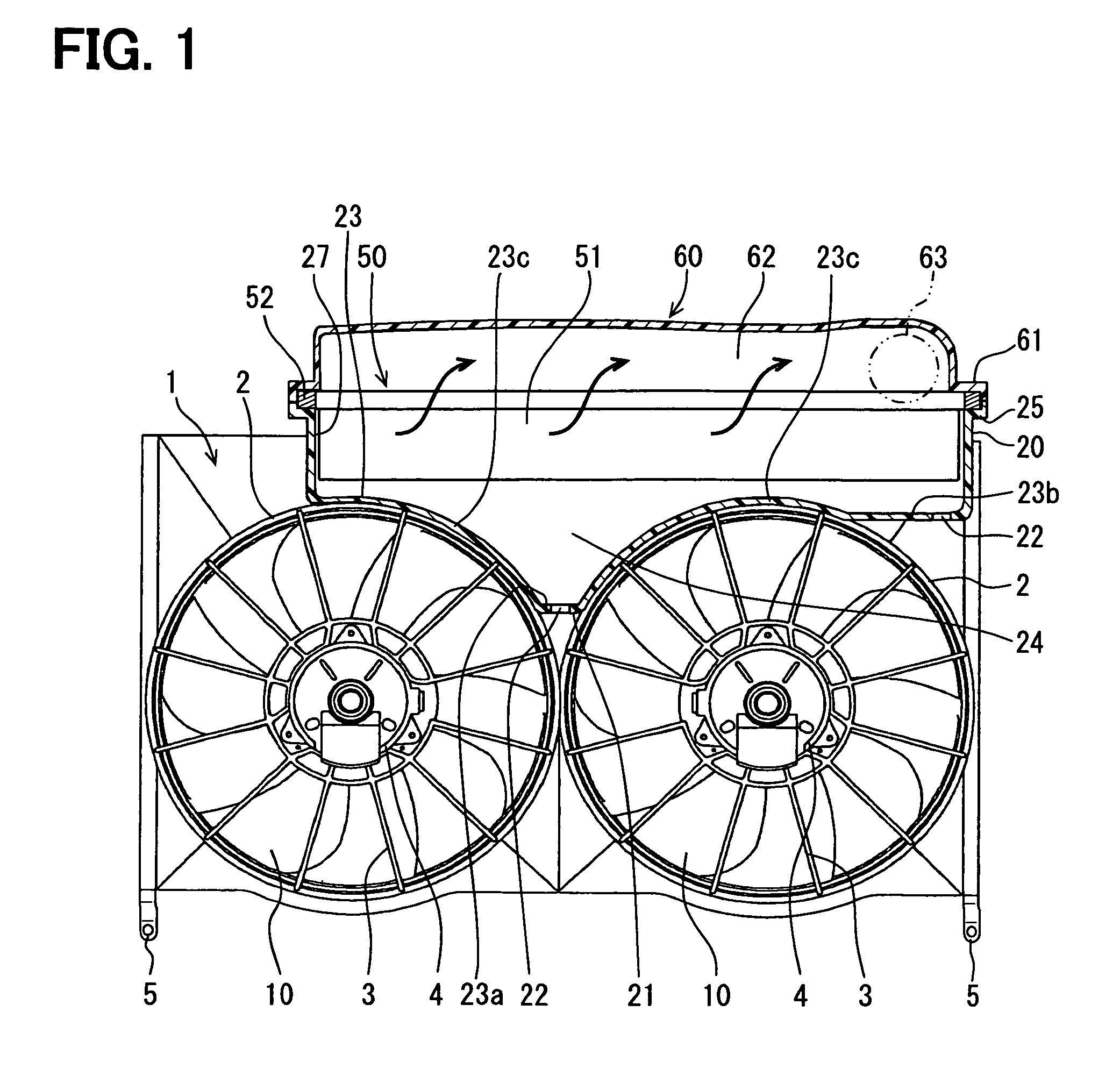
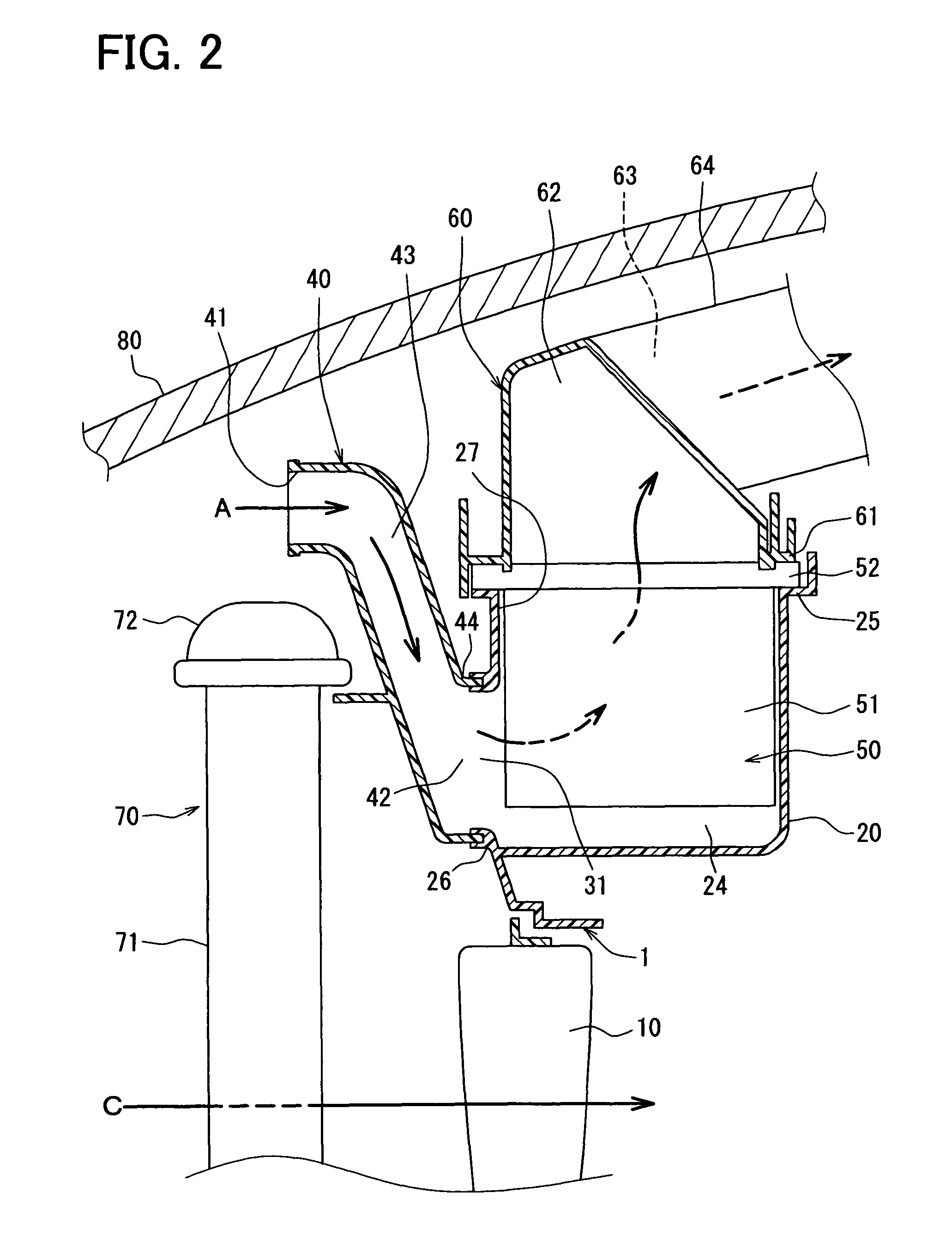
[0025]In a vehicle, fans 10 for supplying a heat exchanger such as a radiator 70 with a cooling air are supported through a fan shroud 1. The fan shroud 1 is, for example, arranged on a rear side of the radiator 70 in an engine compartment. An air cleaner unit 50 for purifying intake air A to be introduced in an engine of the vehicle is integrated with the fan shroud 1.

[0026]The air cleaner unit 50 includes an air cleaner housing 20 integrated with the fan shroud 1, an air cleaner element 50 and a cap member 60. An inlet duct member 40 for suctioning outside air as the intake air is coupled to the air cleaner housing 20. The cap member 60 is coupled to the air cleaner housing 20. The air cleaner element 51 is disposed inside of the air cleaner housing 20 for removing fine particles such as dust from the intake air.

[0027]As shown in FIG. 2. the air cleaner housing 20 has a generally duct shape defining a base rectangular dimension and has a length in a horizontal direction, such as i...

second embodiment

[0074]A second embodiment of the present invention will now be described with reference to FIGS. 7 to 11. In the present embodiment, the fan shroud and the air cleaner housing are formed separately from each other and are integrated with each other. Structures of the present embodiment, except that the fan shroud and the air cleaner housing are separate members, are similar to those of the first embodiment, and thus similar effects are achieved.

[0075]Hereinafter, a procedure for assembling a fan shroud 1A, an air cleaner housing 20A, an inlet duct member 40A and the cap member 60 is described. In the present embodiment, respective parts of the fan shroud 1A, the air cleaner housing 20A and the inlet duct member 40A are denoted with the same reference numerals as the respective parts of the fan shroud 1, the air cleaner housing 20 and the inlet duct member 40 of the first embodiment.

[0076]FIG. 7 is an exploded perspective view of the fan shroud 1A, the air cleaner housing 20A, the ca...


PUM

PropertyMeasurementUnit
volumeaaaaaaaaaa
areaaaaaaaaaaa
resistanceaaaaaaaaaa

Abstract

An air cleaner unit for a vehicle includes an air cleaner element and an air cleaner housing to be arranged generally above ring portions of a fan shroud. The air cleaner element is disposed in the air cleaner housing such that a predetermined space is provided between a lower surface of the air cleaner element and an inner surface of a bottom wall of the air cleaner housing. The bottom wall of the air cleaner housing includes at least two arcuate portions to correspond to the ring portions of the fan shroud and a projecting portion between the arcuate portions. The projecting portion projects downwardly and is configured to increase the volume of the predetermined space.

Description

CROSS REFERENCE TO RELATED APPLICATION[0001]This application is based on Japanese Patent Application No. 2007-304850 filed on Nov. 26, 2007, the disclosure of which is incorporated herein by reference.FIELD OF THE INVENTION[0002]The present invention relates to an air cleaner unit for a vehicle and a fan shroud having the air cleaner unit.BACKGROUND OF THE INVENTION[0003]In general, a fan for supplying heat exchangers, such as a radiator and a condenser, with a cooling air is supported by a fan shroud. For example, Japanese Unexamined Patent Application Publication No. 11-171041 describes a fan shroud integrally having an air cleaner housing.[0004]The described fan shroud form recess parts at an upper portion thereof as the air cleaner housing. Each of the recess parts is open to a rear side of the fan shroud. An air cleaner element for removing fine particles such as dust from air is arranged in the recess part, and a rear opening of the recess part is covered by a cover member. As...

Claims


Application Information

Patent Timeline
Patent Type & Authority Patents(United States)
IPC IPC(8): E04F17/04H02K5/12H02K5/10F04D29/54
CPCF02M35/04F02M35/06F01P5/06F01P11/12
Inventor MAEDA, AKIHIROODA, SHINICHIHIROTA, ATSUSHI
Owner DENSO CORP
Why Eureka
Try Eureka