Circuit breaker having reduced auxiliary trip requirements

a circuit breaker and auxiliary trip technology, applied in the field of circuit breaker, to achieve the effect of reducing tripping requirements

Active Publication Date: 2011-08-16
SCHNEIDER ELECTRIC USA INC
View PDF12 Cites 2 Cited by
  • Summary
  • Abstract
  • Description
  • Claims
  • Application Information

AI Technical Summary

Benefits of technology

[0008]Circuit breakers use free moving bimetallic strips attached to armature / yoke assemblies as a principal means to thermally sense overcurrents and open the circuit breaker contacts (i.e., trip the breaker). The disclosure teaches a yoke stop configured and positioned to reduce tripping requirements of a bimetal equipped circuit breaker and the tripping force required of auxiliary tripping devices such as solenoids.
[0009]The solenoid in a circuit breaker operating in cold temperatures typically has three opposing forces to overcome when tripping the circuit breaker. Namely, an armature biasing force, a frictional engagement force, and a bimetal deflection force. The present disclosure provides circuit breaker configurations and methods for eliminating the effects of the bimetal deflection force in cold temperatures when magnetically tripping the circuit breaker and when using a solenoid to trip the circuit breaker. Put another way, the circuit breaker of the present disclosure includes a yoke stop for absorbing the bimetal deflection force such that the tripping force required to trip the circuit breaker is independent of the bimetal deflection force, thereby reducing the tripping requirements of the circuit breaker.
[0010]Such a reduction of tripping requirements reduces the required solenoid size, which can reduce the overall size of the circuit breaker. Additionally, reducing of the tripping requirements yields a more robust tripping system that is more reliable. Moreover, such reduced tripping requirements provide circuit breakers operable in extreme ambient temperatures, such as, for example, negative thirty-five degrees Celsius or lower.
[0011]Additional benefits of the invention may include the elimination of thermal-assist tripping. Thermal-assist tripping requires more time to clear the circuit than straight magnetic tripping, which may be undesirable. Additionally, the disclosure can be implemented in multi-pole circuit breakers, such as, for example, a three-pole circuit breaker. The disclosure provides methods and apparatuses for reducing the overall tripping requirements such that tripping of one pole is sufficient to trip the other poles without having to rely on thermal-assist tripping or other undesirable methods.

Problems solved by technology

Thermal-assist tripping requires more time to clear the circuit than straight magnetic tripping, which may be undesirable.

Method used


Image

  • Circuit breaker having reduced auxiliary trip requirements
  • Circuit breaker having reduced auxiliary trip requirements
  • Circuit breaker having reduced auxiliary trip requirements

Examples


Embodiment Construction

[0018]Although the invention will be described in connection with certain preferred embodiments, it will be understood that the invention is not limited to those particular embodiments. On the contrary, the invention is intended to include all alternatives, modifications and equivalent arrangements as may be included within the spirit and scope of the invention as defined by the appended claims.

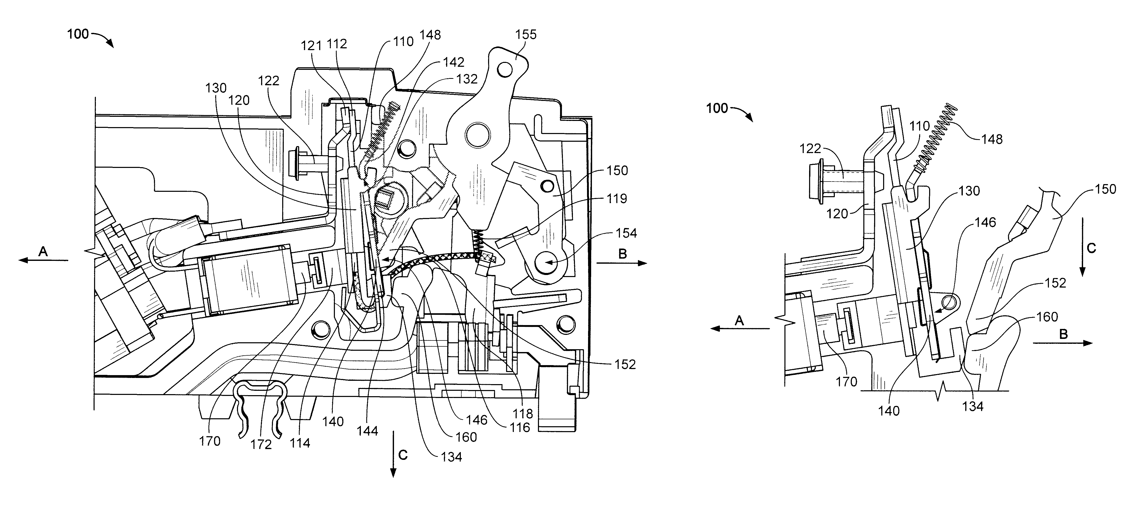
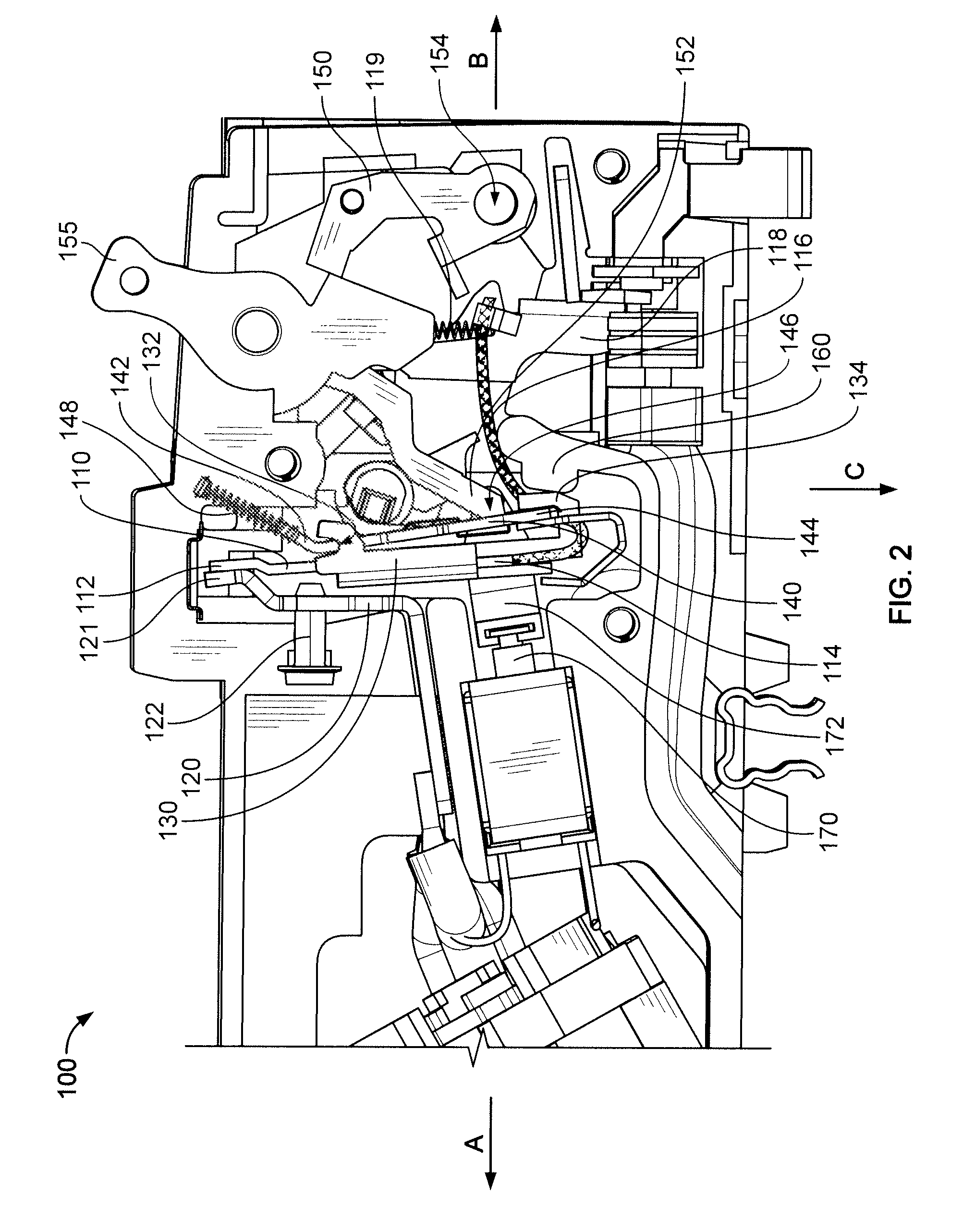
[0019]Referring now to the drawings and initially to FIG. 2, there is shown a circuit breaker 100 that includes a bimetal 110 attached to a load terminal 120 at a load end 112 of the bimetal 110 and to a yoke 130 at a free end 114 of the bimetal 110. The free end 114 of the bimetal is attached to a flexible pigtail conductor 116 such that the bimetal 110 is directly heated by the attached pigtail conductor 116. According to some embodiments, the circuit breaker is a miniature circuit breaker with an overall width of a housing of the circuit breaker being about 1 inch or smaller, preferably ab...


PUM


Abstract

A bimetal in a circuit breaker can deflect in a first direction or a second direction depending upon conditions. If the bimetal deflects in the second direction it can increase the force necessary to operate a trip mechanism of the circuit breaker. A yoke stop helps to control bimetal deflection forces and thus, the amount of force necessary to operate the trip mechanism. This allows better control, size, and selection of operating parts for the circuit breaker.

Description

FIELD OF THE INVENTION[0001]This invention is directed generally to a circuit breaker, and, more particularly, to a circuit breaker having reduced auxiliary trip requirements.BACKGROUND OF THE INVENTION[0002]Circuit breakers provide automatic current interruption to a monitored circuit when undesired fault conditions occur. These fault conditions include, for example, arc faults, overloads, ground faults, and short-circuits. Referring to FIG. 1, a portion of an exemplary prior art circuit breaker 1 is shown. In the circuit breaker 1, an overcurrent is detected when the fault current generates sufficient heat in a terminal 20 and a bimetal 10 to cause the bimetal 10 to deflect and / or bend. The mechanical deflection triggers a trip assembly that includes a spring-biased trip lever 50 to force a moveable contact attached to a moveable conductive blade away from a stationary contact, thereby breaking the circuit. When the circuit is exposed to a current above that level for a predetermi...

Claims


Application Information

Patent Timeline
Patent Type & Authority Patents(United States)
IPC IPC(8): H01H81/00H01H83/00H01H75/12H01H77/00H01H75/00
CPCH01H71/162H01H71/405H01H83/20H01H71/7436H01H2071/124
Inventor BROGHAMMER, WILLIAM J.WOODSON, CAMERON L.
Owner SCHNEIDER ELECTRIC USA INC
Why Eureka
Try Eureka