
Zoom lens

a zoom lens and lens body technology, applied in the field of lenses, can solve the problems of increasing the cost of aspheric lenses is larger, and the cost of zoom lenses is larger, so as to achieve the effect of reducing the difficulty of fabrication and assembly and cos

Inactive Publication Date: 2011-08-16
YOUNG OPTICS
View PDF10 Cites 9 Cited by
  • Summary
  • Abstract
  • Description
  • Claims
  • Application Information

AI Technical Summary

Benefits of technology

[0006]Accordingly, the invention is directed to a zoom lens, which has at least one of lower cost and lower difficulty in fabrication and assembly.
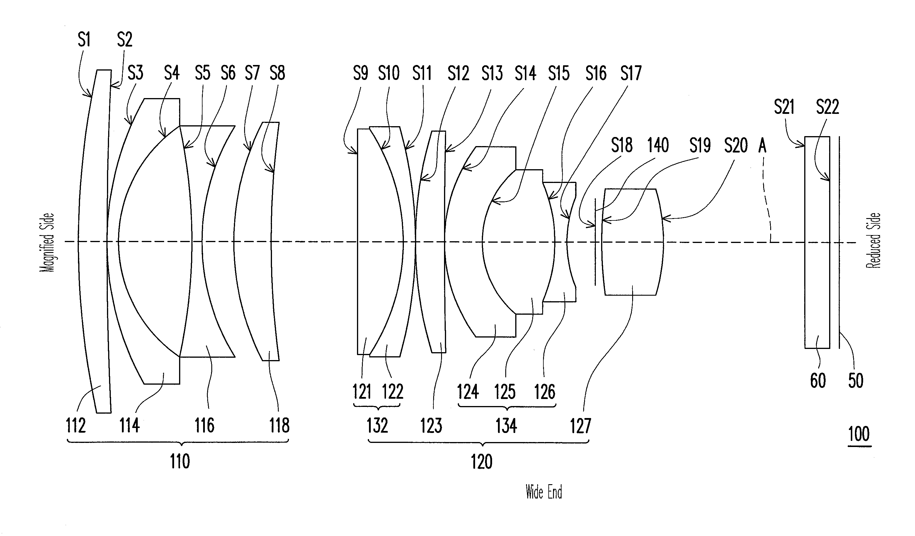
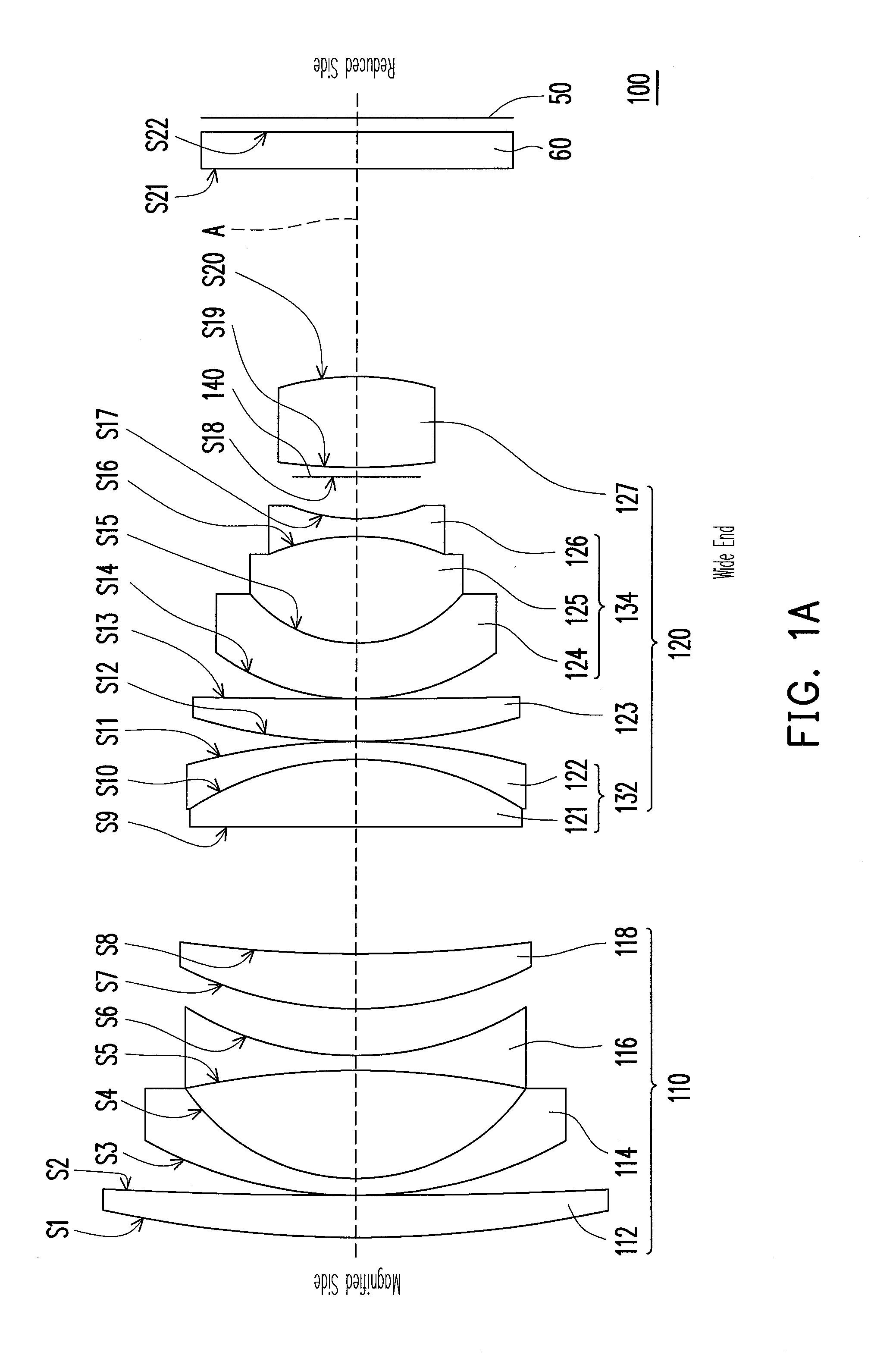
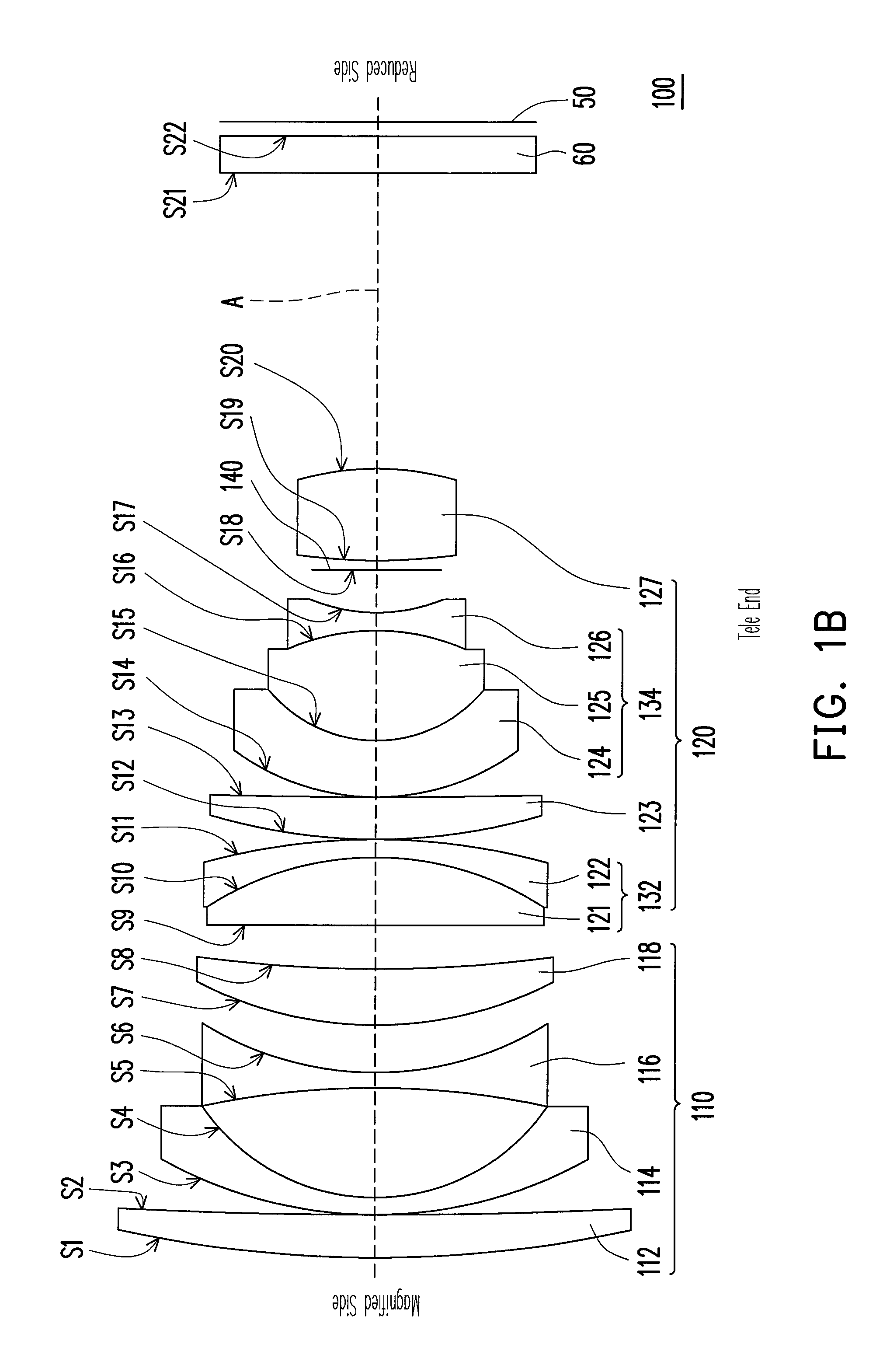
[0008]The embodiment or the embodiments of the invention may have at least one of the following advantages, in the zoom lens according to the embodiment of the invention, two lens groups and eleven lenses are used, which effectively reduces the cost of the lenses and the mechanisms in the zoom lenses and reduces the difficulty in fabricating lenses and assembling lenses.

Problems solved by technology

However, the aspheric lenses have little tolerance, thereby increasing the difficulty in fabrication and assembly.
Moreover, the aspheric lenses have larger cost.
However, the more the zooming lens groups are, the larger the cost of the zoom lens is.

Method used


Image

  • Zoom lens
  • Zoom lens
  • Zoom lens

Examples


Embodiment Construction

[0014]In the following detailed description of the preferred embodiments, reference is made to the accompanying drawings which form a part hereof, and in which are shown by way of illustration specific embodiments in which the invention may be practiced. In this regard, directional terminology, such as “top,”“bottom,”“front,”“back,” etc., is used with reference to the orientation of the Figure(s) being described. The components of the invention can be positioned in a number of different orientations. As such, the directional terminology is used for purposes of illustration and is in no way limiting. On the other hand, the drawings are only schematic and the sizes of components may be exaggerated for clarity. It is to be understood that other embodiments may be utilized and structural changes may be made without departing from the scope of the invention. Also, it is to be understood that the phraseology and terminology used herein are for the purpose of description and should not be ...


PUM


Abstract

A zoom lens including a first lens group and a second lens group arranged in sequence from a magnified side toward a reduced side is provided. The first lens group has a negative refractive power and includes a first lens, a second lens, a third lens, and a fourth lens arranged in sequence from the magnified side toward the reduced side, of which the refractive powers are respectively positive, negative, negative, and positive. The second lens group has a positive refractive power and includes a fifth lens, a sixth lens, a seventh lens, an eighth lens, a ninth lens, a tenth lens, and an eleventh lens arranged in sequence from the magnified side toward the reduced side, of which the refractive powers are respectively positive, negative, positive, negative, positive, negative, and positive. The eighth lens, the ninth lens, and the tenth lens together form a triple cemented lens.

Description

BACKGROUND OF THE INVENTION[0001]1. Field of the Invention[0002]The invention generally relates to a lens, and more particularly, to a zoom lens.[0003]2. Description of Related Art[0004]The zoom lens is a common optical component of an optical system, which may be used in a wide variety of applications including digital cameras, back projection televisions, projectors, or the like. In general zoom lenses, aspheric lenses are used for reducing the total number of the lenses in a zoom lens, such as U.S. Pat. Nos. 6,738,196, 7,061,688, and 6,147,812. However, the aspheric lenses have little tolerance, thereby increasing the difficulty in fabrication and assembly. Moreover, the aspheric lenses have larger cost. Other zoom lenses adopt more zooming lens groups for reducing the total number of the lenses in a zoom lens, and avoid using aspheric lenses, such as U.S. Pat. Nos. 6,906,867, 6,894,845, and 6,137,638. However, the more the zooming lens groups are, the larger the cost of the zoom...

Claims


Application Information

Patent Timeline
Patent Type & Authority Patents(United States)
IPC IPC(8): G02B15/00G02B15/14
CPCG02B15/177G02B15/1425
Inventor CHOU, YU-HUNGCAI, YUAN-LONGTSENG, CHIEN-HSIUNG
Owner YOUNG OPTICS
Learn More