Charging member, charging device, image forming apparatus, and process cartridge

a charging device and charging device technology, applied in electrographic process apparatus, corona discharge, instruments, etc., can solve the problems of shortening the life of the photosensitive drum b>100, image failure, uneven image density and scumming, etc., to reduce the adhesiveness of soiling microparticles, minimize non-uniform charging, and reduce the effect of uneven image density

Inactive Publication Date: 2011-08-16
CANON KK
View PDF8 Cites 3 Cited by
  • Summary
  • Abstract
  • Description
  • Claims
  • Application Information

AI Technical Summary

Benefits of technology

[0019]The present invention reduces adhesiveness of soiling microparticles. The present invention also provides a charging member, a charging device, an image forming apparatus, and a process cartridge that minimize nonuniform charging due to soiling microparticles, that do not cause image failure, such as unevenness in image density and scumming, and that output good images through the life of the charging member.

Problems solved by technology

This shortens the life of the photosensitive drum 100.
However, the charging roller is soiled with a soiling substance through repetitive image forming processes, and nonuniform charging resulting from the soiled charging member sometimes causes image failure such as unevenness in image density and scumming.
Adhesion of soiling microparticles causes local unevenness in potential on the photosensitive drum, and this is one of the factors that cause image failure such as nonuniform density and scumming.
For this reason, there has been a demand for a charging member onto which soiling microparticles do not easy adhere.
On the other hand, since a uniforming effect of an AC component is not provided, unevenness in potential is easily caused on the photosensitive drum by soiling of the charging roller, and image failure easily occurs.
In addition, in the image forming apparatus using the cleaner-less method, the charging roller is exposed to more soiling substances.

Method used


Image

  • Charging member, charging device, image forming apparatus, and process cartridge
  • Charging member, charging device, image forming apparatus, and process cartridge
  • Charging member, charging device, image forming apparatus, and process cartridge

Examples


first embodiment

[0032]A charging member, a charging device including the charging member, a process cartridge including the charging member, and an image forming apparatus according to a first embodiment of the present invention will be described in detail below with reference to the drawings.

(1) Outline of Configuration and Operation of Image Forming Apparatus

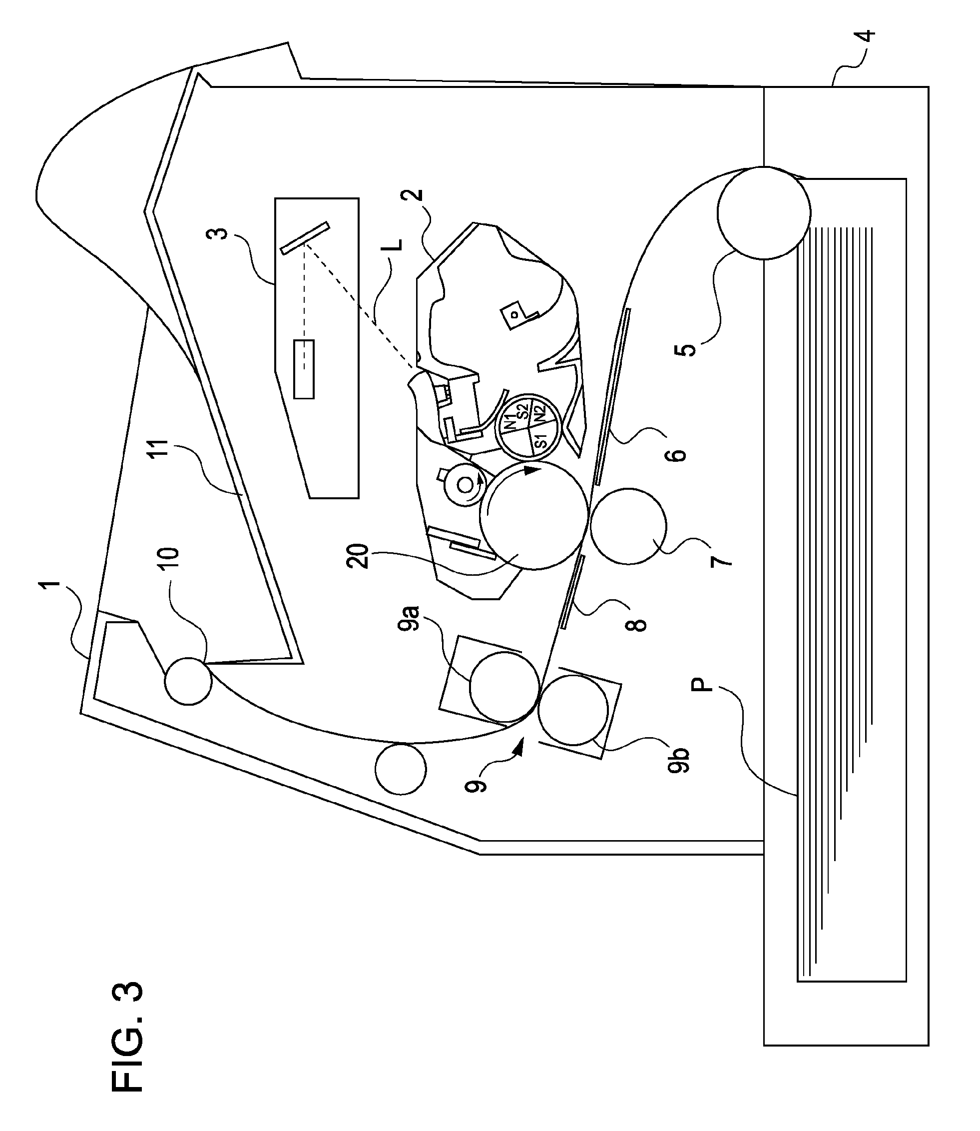
[0033]FIG. 3 schematically shows a configuration of an image forming apparatus according to the first embodiment. This image forming apparatus is an electrophotographic laser beam printer in which a process cartridge is mounted removably. An external host apparatus (not shown), such as a personal computer or an image reader, is connected to the printer. The printer outputs a print according to image information input from the host apparatus to a controller (not shown). The controller exchanges signals with the host apparatus. The controller also exchanges signals with an image forming device to control an image forming sequence.

[0034]The prin...

second embodiment

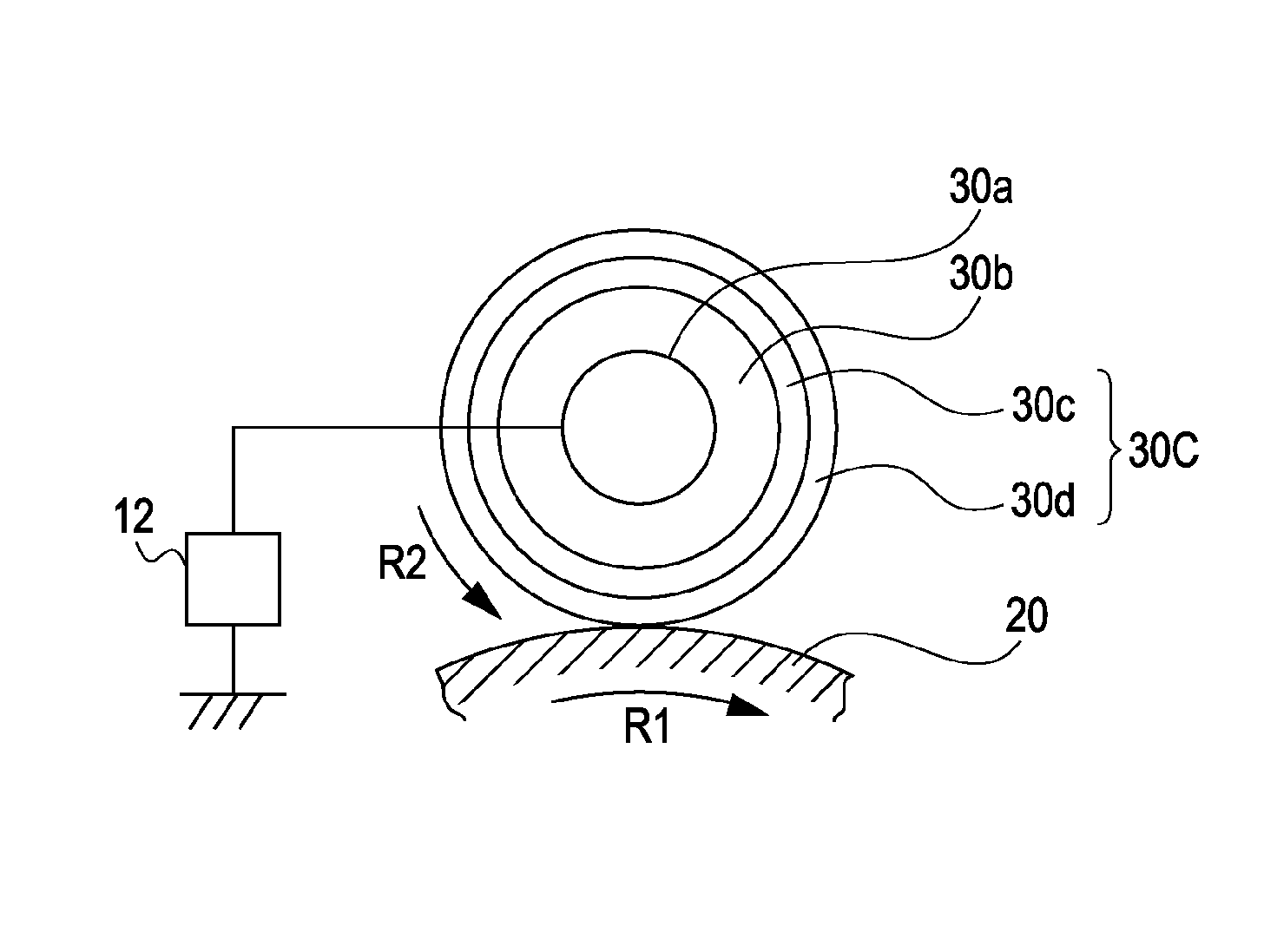
[0101]A second embodiment realizes space saving by decreasing the outer diameter of a charging roller 30. Since structures of the second embodiment other than the outer diameter of the charging roller 30 and pressure springs 31 for pressing the charging roller 30 against a photosensitive drum 20 are similar to those adopted in the first embodiment, descriptions thereof are omitted.

[0102]In the second embodiment, the charging roller 30 has an outer diameter of 8 mm. Since the outer circumference of the charging roller 30 is thereby decreased, the number of soiling substances per unit area on the surface of the charging roller 30 increases.

[0103]Further, rigidity of the charging roller 30 is decreased by reducing the outer diameter of the charging roller 30. In the second embodiment, the entire longitudinal area of the charging roller 30 can be pressed against the photosensitive drum 20 with a sufficient contact pressure by setting the total pressure of the pressure springs 31 against...


PUM


Abstract

The present invention provides a charging member, a charging device, an image forming apparatus, and a process cartridge that minimize local unevenness in potential of a charged object resulting from soiling of the charging member with soiling microparticles or soiling aggregates, that do not cause image failure such as unevenness in image density and scumming, and that output good images through the life of the charging member. The charging member charges a surface of the object by receiving a voltage while being in contact with the object, and satisfies the condition that Rzjis≦30 and Rsk≦0, where Rzjis represents the ten-point average roughness of a surface of the charging member in contact with the object and Rsk represents the skewness of a roughness curve.

Description

BACKGROUND OF THE INVENTION[0001]1. Field of the Invention[0002]The present invention relates to a charging member, a charging device, an image forming apparatus, and a process cartridge.[0003]Here, an image forming apparatus refers to an apparatus that forms an image on a recording medium by an electrophotographic image forming method. Examples of image forming apparatuses are an electrophotographic copying machine, an electrophotographic printer (e.g., a laser beam printer or an LED printer), a facsimile machine, and a word processor.[0004]A process cartridge refers to a cartridge serving as a process unit into which at least a charging device and an electrophotographic photosensitive member are combined, and which is removably mounted in a main body of the image forming apparatus.[0005]2. Description of the Related Art(1) Image Forming Process[0006]FIG. 2 schematically shows a configuration of an image forming apparatus of the related art. This image forming apparatus is an elect...

Claims


Application Information

Patent Timeline
Patent Type & Authority Patents(United States)
IPC IPC(8): G03G15/02
CPCG03G15/0233
Inventor KATO, MASAHITONAITO, NORIHITOKIHARA, TAKAYOSHIKASE, TAKASHI
Owner CANON KK
Why Eureka
Try Eureka