
Bite block assembly for endotrachial tube

a technology of endotracheal tubes and block assemblies, which is applied in the field of medical devices, can solve the problems of block dislodged, critical interruption of gas flow to the patient, and sliding down the trachea of the patien

Inactive Publication Date: 2011-08-23
SOUTHMEDIC
View PDF9 Cites 23 Cited by
  • Summary
  • Abstract
  • Description
  • Claims
  • Application Information

AI Technical Summary

Benefits of technology

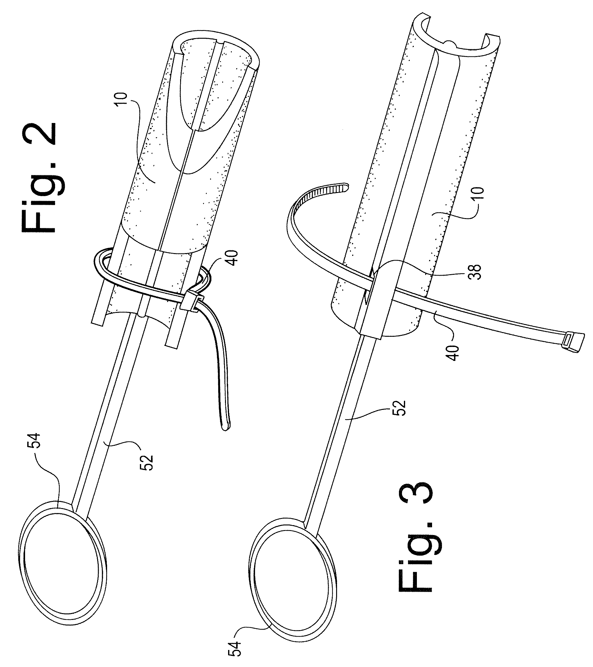
"The invention is an improved bite block for an endotracheal tube that includes a hollow cavity for receiving the tube. The bite block has a forward and rearward end, with an inwardly curved wall that rises upwardly from a base. The bite block has a flexible arm that protrudes from the rearward end and a tether to engage the endotracheal tube. The arm flexes about an arc when the tube is inserted, causing the tether to encircle the tube and grip it securely. The bite block can be easily attached to the endotracheal tube and securely holds it in place during use. The invention also includes a slot in the bite block for inserting a tie strap for connecting the gas supply tube to the endotracheal tube. The bite block can be used with different sizes of endotracheal tubes."

Problems solved by technology

A sufficiently hard bite on a tube can pinch or even rupture the tube, thereby critically interrupting the gas flow to the patient.
When a bite block is used, it is critical that that it not become disengaged from the tube or that the tube slide within the block, since this can result in the block becoming dislodged or even in some cases sliding down a patient's trachea.
While a typical bite block is dimensioned to accommodate even a relatively narrow endotracheal tube, slippage of the tube (especially a narrow tube) within the block can still occur.
However, especially when used with a smaller diameter endotracheal tube, it is still possible for slippage of the bite block to occur, in particular if the caregiver neglects to properly cinch the bite block to the endotrachial tube with the supplied strap, or in situations when the use of a strap is not practical.

Method used


Image

  • Bite block assembly for endotrachial tube
  • Bite block assembly for endotrachial tube
  • Bite block assembly for endotrachial tube

Examples


Embodiment Construction

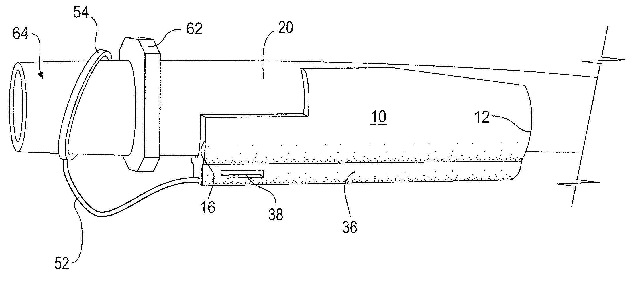
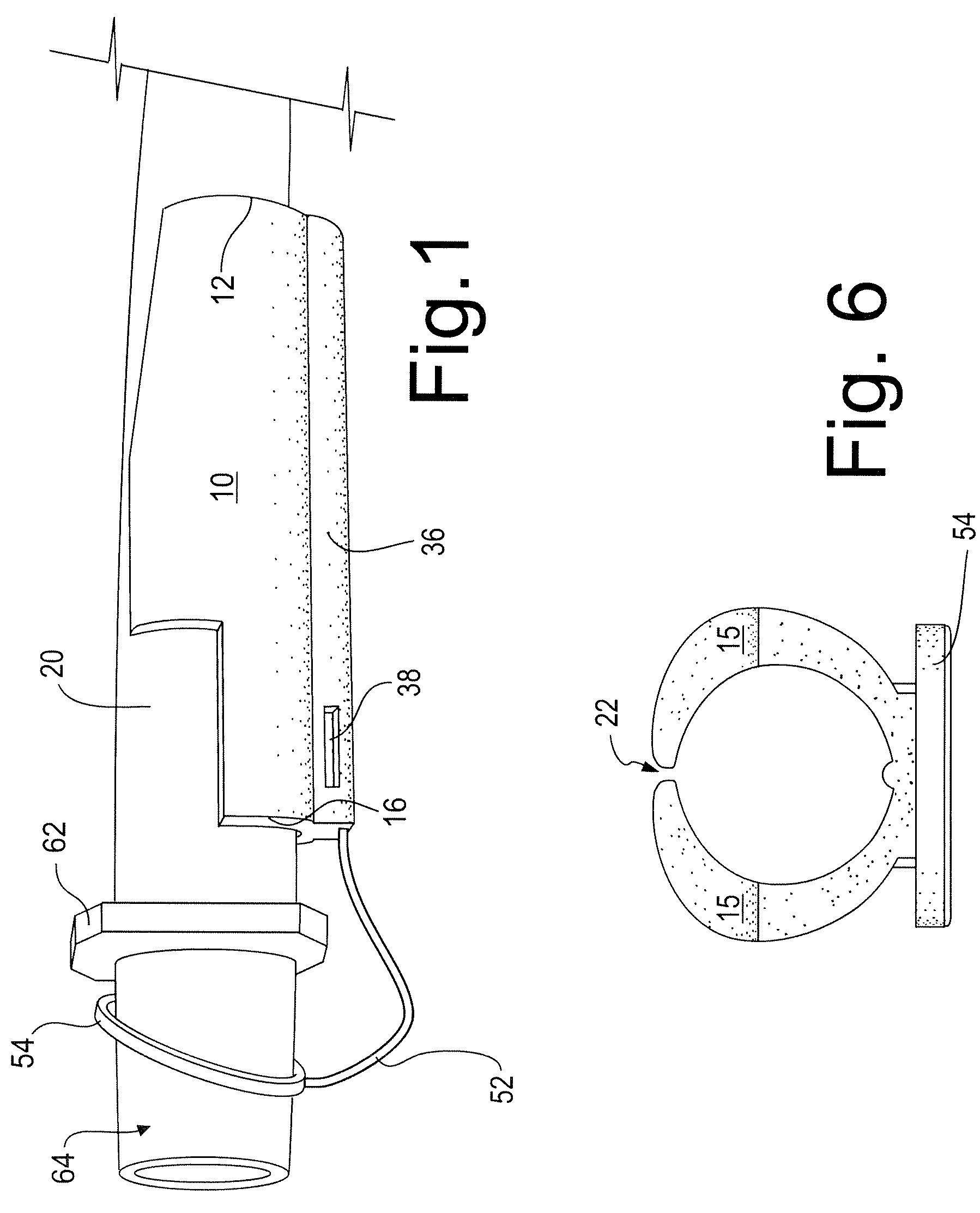
[0028]Turning to the figures, a bite block according to the present invention consists of a generally tubular body 10, having opposed forward and rearward ends 12 and 16 respectively. When an endotracheal tube 20 is installed within the bite block, the forward end faces towards the outlet end 14 of the endotracheal tube 20 and the rearward end 16 faces the inlet end 18 of the endotracheal tube 20. When inserted into the mouth of a patient, the forward end 12 of the bite block is inserted in the patient's mouth, while the rearward end 16 protrudes outwardly from the patient's teeth. The bite block is formed from a semi-rigid molded plastic such as PVC, TPU or TPE. The material is selected to provide sufficient resiliency to permit the walls of the body to flex so as to grip an endotracheal tube, as will be described below. As well, the body 10 should have sufficient resiliency and softness to provide adequate patient comfort.

[0029]As seen more particularly in FIGS. 4, 5 and 6, the bo...


PUM


Abstract

A bite block for an endotrachial tube includes a hollow body extending between open ends to receive an endotrachial tube such that opposing ends of the tube protrude through the open ends of the bite block. The bite block includes a tether to retain the bite block to the tube to prevent unwanted separation or movement of the tube within the bite block. The tether consists of a flexible arm which protrudes rearwardly from the bite block towards the inlet end of the tube and terminates in a ring configured to encircle the endotrachial tube, thereby effectively tethering the bite block to the tube. The arm and ring are configured such that the arm flexes in an arc when tethering the tube, thereby permitting the ring to engage the tube when fitted to thereto.

Description

FIELD OF THE INVENTION[0001]The invention generally relates to medical devices, and more particularly to a bite block assembly for an endotracheal tube.BACKGROUND OF THE INVENTION[0002]Endotracheal tubes, used in various medical procedures for delivering gas to a patient, generally consist of a long tube which may be inserted into a patient's mouth and down the trachea to provide an air supply to a patient. The use of an endotrachial tube ensures that the airway is not closed off and that air is able to reach the lungs. Typically, the tube is flexible and somewhat resilient in order to easily bend through the airway of a patient and not cause tissue damage. It is often desirable to incorporate a bite block with the tube, in order to prevent a patient from biting down on the tube. The bite block consists of a relatively rigid member having a hollow interior to which encircles the tube at its upper (inlet) end where the tube enters the patient's mouth. The bite block is inserted into ...

Claims


Application Information

Patent Timeline
Patent Type & Authority Patents(United States)
IPC IPC(8): A61M11/00
CPCA61M16/0488A61M16/0493
Inventor MCDONALD, LEEHAJGATO, JULIUSNOSEWORTHY, KENNETH
Owner SOUTHMEDIC
Learn More